30
Installation
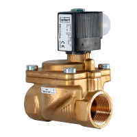
Type 3280, 3285
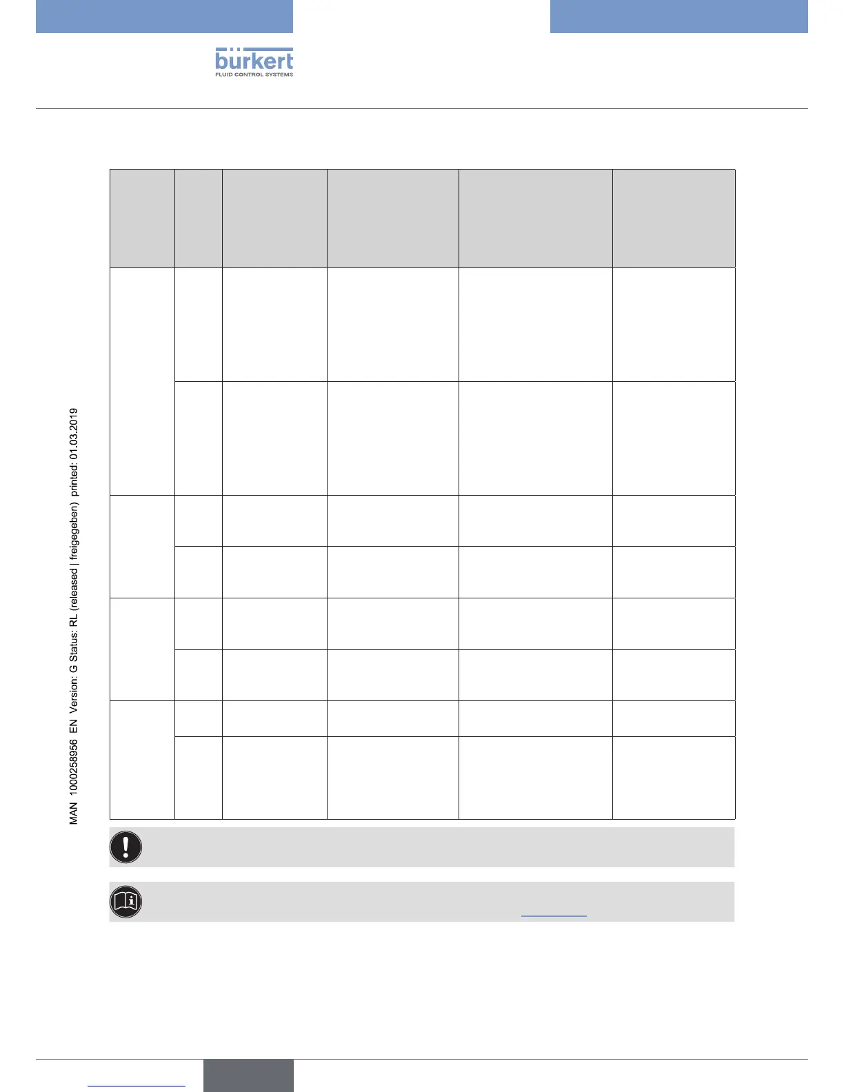
Description of the function
DIP
switches
Posi-
tion
Function for the
on-off
Function for the
control valve
Function for the
standard version
PWM version
Function for the
positioner and
process controller
version (applies
to analog version
only)
1 OFF Normal oper-
ating direction
of the set-point
value 10...30 V
= valve opens
Normal operating
direction of the set-
point value (e.g. set-
point value 4...20 mA
corresponds to
position 0...100 %),
increasing
Normal operating
direction of the set-point
value (PWM duty cycle
0–100 % corresponds
to position 0–100 %),
increasing
no function
ON Reversal of
the operating
direction of the
set-point value
10...30 V = valve
closes
Reversal of the oper-
ating direction of the
set-point value (e.g.
set-point value 20...4
mA corresponds to
position 0...100 %),
decreasing
Reversal of the operating
direction of the set-point
value (PWM duty cycle
0–100 % corresponds
to position 0–100 %),
decreasing
no function
2 OFF no function Set-point value input
4...20 mA
no function no function
ON no function Set-point value input
0...10 V
no function no function
3 OFF Valve actuating
speed: normal
mode
Valve actuating
speed: normal mode
Valve actuating speed:
normal mode
büS
ON Valve actuating
speed: slow
mode
Valve actuating
speed: slow mode
Valve actuating speed:
slow mode
CANopen
4 OFF Low power
function: off
Low power function:
off
Low power function: off no function
ON Low power
function: on,
lower force, less
heat generation
in the valve
Low power function:
on, lower force, less
heat generation in the
valve
Low power function: on,
lower force, less heat
generation in the valve
no function
Whether the device is a PWM version can be found on the type label.
The change in function does not become effective until the supply voltage is applied again.
A more precise description of the functions can be found in chapter “8 Start-up”.