Table of Contents
2 / 68 0870211676_RA0760A_PLUS_-0004_IM_en
Table of Contents
1 Safety .......................................................................................................................................4
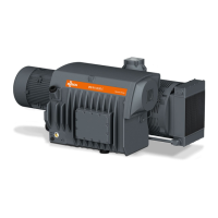
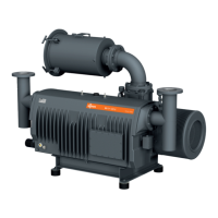
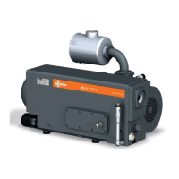
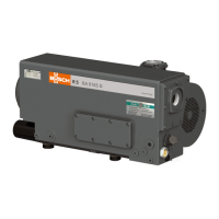
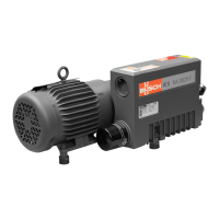
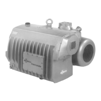
2 Product Description ..................................................................................................................5
2.1 Operating Principle .......................................................................................................... 7
2.2 Application....................................................................................................................... 7
2.3 Standard Features ............................................................................................................ 7
2.3.1 User Interface........................................................................................................7
2.3.2 Acoustic Cabinet ................................................................................................... 7
2.3.3 Control Unit .......................................................................................................... 7
2.3.4 Monitoring Devices ............................................................................................... 8
2.3.5 I/O and Communication Port ................................................................................8
2.3.6 Gas Ballast Valve ................................................................................................... 8
2.3.7 Inlet Filter ..............................................................................................................8
2.4 Optional Accessories ........................................................................................................ 8
2.4.1 Inlet Filter Condition Monitoring Kit ...................................................................... 8
2.4.2 Water-Oil Heat Recovery Unit............................................................................... 8
2.5 P&ID "Piping and Instrumentation Diagram"................................................................... 9
2.6 LED Indicators .................................................................................................................. 9
2.7 Description of User Interface Functions ............................................................................ 10
2.7.1 Menu Overview .................................................................................................... 10
2.7.2 Bottom Bar ............................................................................................................11
2.7.3 Navigation............................................................................................................. 11
2.7.4 Role and User........................................................................................................12
2.7.5 System Settings ..................................................................................................... 13
2.7.6 Machine and Software Identification ..................................................................... 14
2.7.7 Ethernet Settings ................................................................................................... 14
2.8 Web Visualization ............................................................................................................ 15
3 Transport ..................................................................................................................................18
4 Storage .....................................................................................................................................19
5 Installation................................................................................................................................20
5.1 Installation Conditions...................................................................................................... 20
5.2 Connecting Lines / Pipes .................................................................................................. 21
5.2.1 Suction Connection ............................................................................................... 21
5.2.2 Discharge Connection ........................................................................................... 21
5.2.3 Cooling Water Connection (Optional) ................................................................... 22
5.2.4 Inlet Filter Condition Monitoring Kit ...................................................................... 23
5.2.5 External Inlet Pressure Sensor ................................................................................ 24
5.3 Filling Oil.......................................................................................................................... 25
5.4 Fitting the Coupling ......................................................................................................... 26
5.5 Electrical Connection ........................................................................................................ 27
5.5.1 Wiring Diagram Control Unit................................................................................. 28
6 Commissioning.........................................................................................................................29
6.1 Prerequisites Before Use ................................................................................................... 29
6.2 Configuration................................................................................................................... 29
6.3 Start Up ........................................................................................................................... 30
7 In Operation .............................................................................................................................31
7.1 Control Mode .................................................................................................................. 31
7.1.1 Local/Manual ........................................................................................................ 32
7.1.2 Local/Auto "Week Planner".................................................................................. 32
7.1.3 Remote/Auto ........................................................................................................ 33