Assembly & Operation Manual
BVM © 2009 K5300-Current_manual-090808.doc Page 15 12/2/2009
Use a JR Matchmaker or a radio system to center the aileron servos and install trimmed double-arm,
three holed servo arms. The linkage system is designed such that the servo arms are offset one
tooth, or 10-12 degrees forward while the servo is centered.
Use a 12” long 1/16” drill to allow the front servo screws to
enter at a slight angle. See the Helpful Hint below if a long
reach drill is not available.
After routing the aileron servo lead to the flap servo pocket,
install the four #2 servo screws. Use a high quality ball driver
to avoid stripping the head of the screws. A small notch can
be made in the servo cover flange to allow more motion if an
“L” wrench is used.
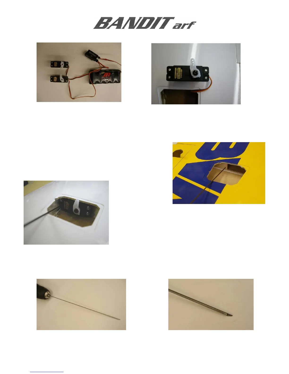
Helpful Hint: If a long reach 1/16” drill is not available, one can be made using the piece of 1/16”
music wire (included in the nose gear door package) with a flat point ground on the tip. Use a belt
sander to grind an angled flat point; the sharp edges will act as the drill cutters.