Assembly & Operation Manual
BVM © 2009 K5300-Current_manual-090808.doc Page 16 12/2/2009
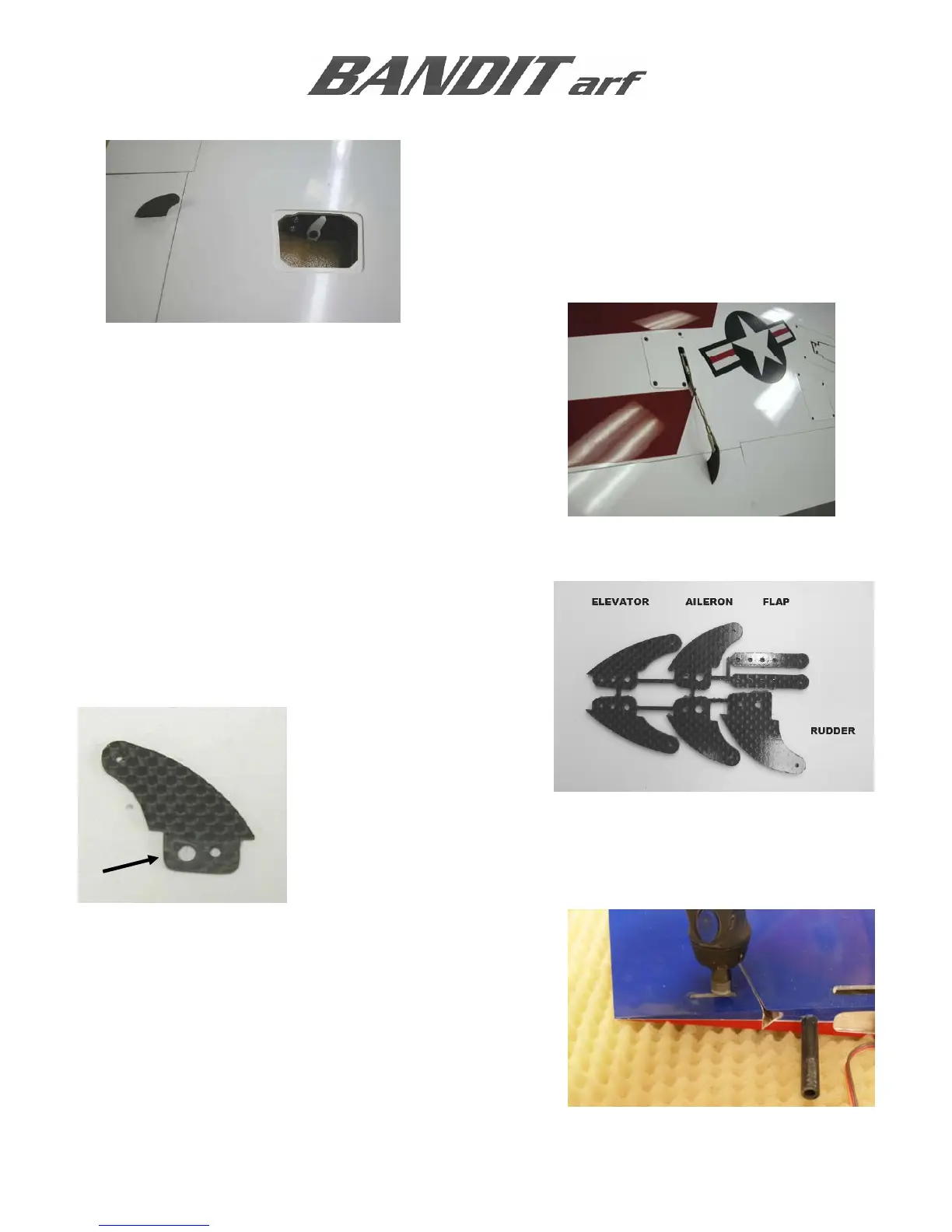
This is the completed aileron servo and control horn
installation. Note that the servo arm is rotated forward one
tooth, approximately 10 degrees.
NOTE: The following section covers the installation of the
CF control horn.
Helpful Hint: If two channels for aileron operation are
used, sub trim can be used to fine-tune the aileron servos
independently. The amount of differential can be adjusted
by simply adjusting ATV.
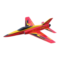
AILERON CONTROL HORNS
The control horns are router cut carbon fiber. They are
easily distinguished by the number of holes in the base
and outline shape. Use a cut-off disk to separate the
parts.
Always scuff the gluing surfaces, and clean the clevis hole with a sharp
1/16” drill prior to installation.
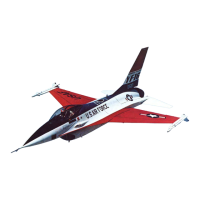
Use a 1/16” carbide cutter BVM #2142 to make a slot in
the control surface as indicated by the pen mark. Set the
carbide cutter to the appropriate depth by comparing it to
the length of the control horn’s base. The photo shows the
elevator, but the process is similar.