Assembly & Operation Manual
BVM © 2009 K5300-Current_manual-090808.doc Page 28 12/2/2009
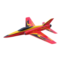
Use a 1/16” drill bit to drill the (4) servo mounting holes
Install the servo with the servo arm rotated
forward back on itself. Once in place rotate the
arm through the stabilizer skin.
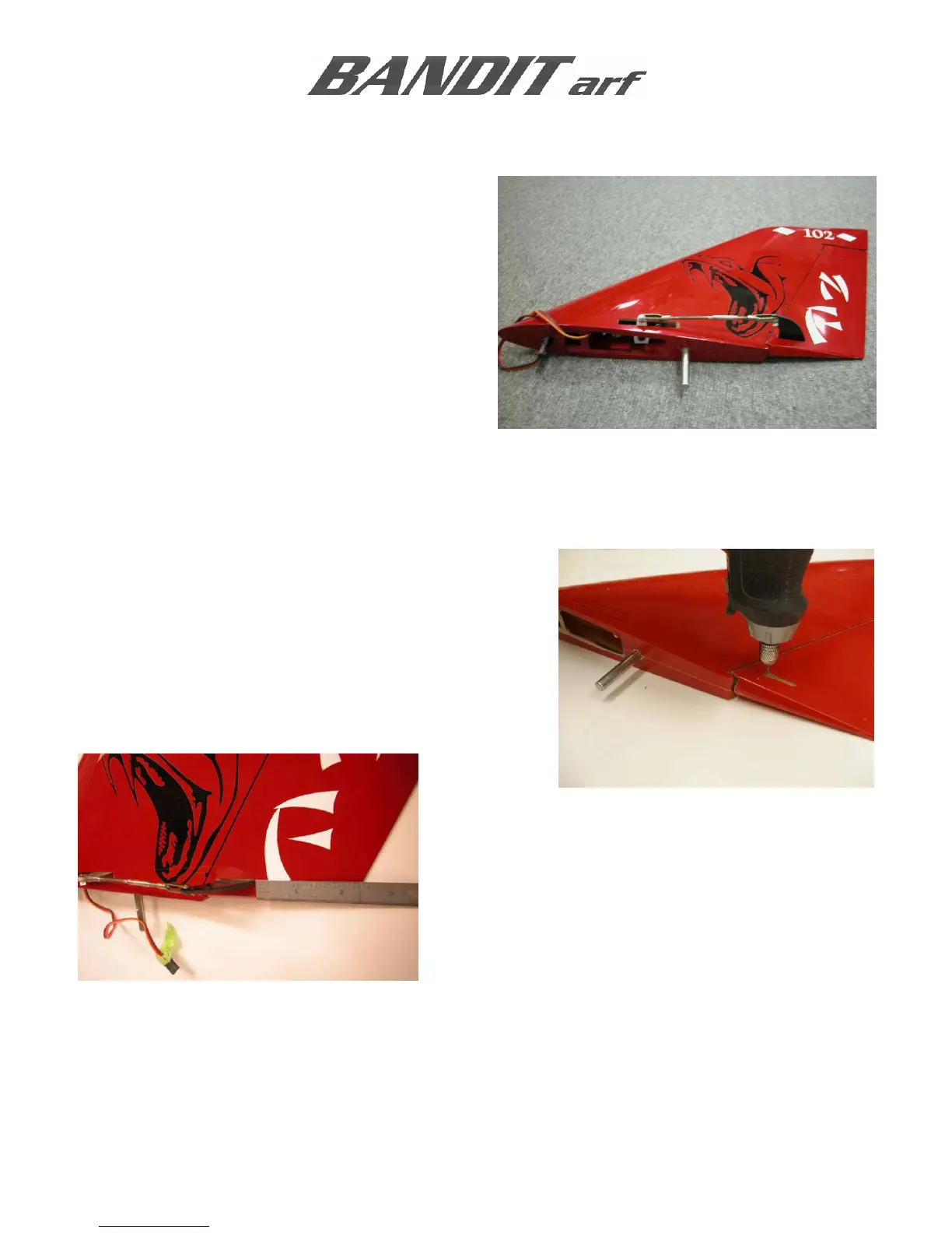
RUDDER CONTROL HORN
Always scuff the gluing surfaces, and clean the clevis hole with a sharp 1/16” drill prior to installation.
Use a 1/16” carbide cutter to make a slot in the control
surface as marked. Set the carbide cutter to the
appropriate depth by comparing it to the length of the
control horn’s base similar to the elevator control horn.
Use a Perma-Grit flat file to adjust and fine-tune the
control horn slot.
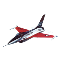
The trailing edge of the rudder horn is designed to be
2-3/8” from the trailing edge of the rudder. Make sure
the horn sits flat on the skin surface
Once the fit and alignment of the control horn are
established, place masking tape around the perimeter
of the slot; leaving a 1/16” gap on the sides to allow
for a fillet of AeroPoxy.
Apply AeroPoxy into the slot and the holes on the base of the of the control horn. Push the scuffed
control horn into the surface, and wipe the excess glue away leaving a small fillet.
Pull the surrounding tape from the control horn and clean and glue residue from the painted surface.
Use a long piece of masking tape stretched over the center of the control horn to hold in position
while the AeroPoxy cures.