Assembly & Operation Manual
BVM © 2009 K5300-Current_manual-090808.doc Page 36 12/2/2009
The bottom of the inlets should be 2.15” from the bottom of the fuselage. Measure at the centerline.
Use the supplied 1/8” ply template for a quick reference.
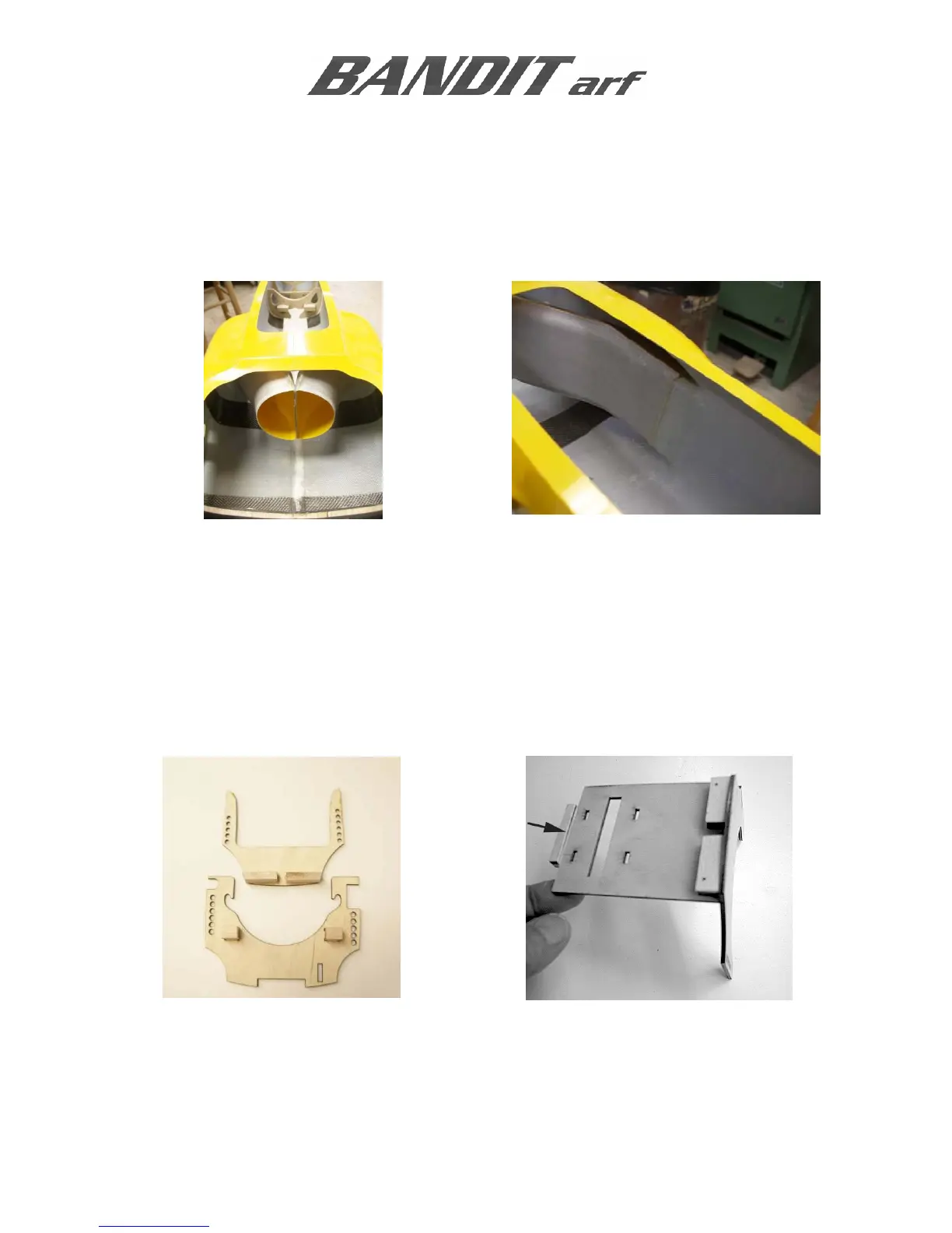
After both inlets are installed, temporarily fit the inlet extension over the rear of the inlets. Add a few
drops of SLO-ZAP to hold the rear of the inlets together. Be careful to not glue the inlet extension to
the inlets; the extension will be glued to the bypass later.
Apply additional SLO-ZAP to help secure the inlet to fuselage joint. Allow the glue to run around the
inlet.
NOSE GEAR STEERING SERVO TRAY, PUMP MOUNT, F2, AND F3
Use the following photos to assemble and position these parts.
#2 screws are used to hold the fuel pump mount to F3.
#2 servo screws are used to hold the steering servo tray in to F1 and F2