Assembly & Operation Manual
BVM © 2009 K5300-Current_manual-090808.doc Page 41 12/2/2009
BYPASS
NOTE: Use the 3” fiberglass extension for the smaller P-60/P-70 bypass. Trim the 3” fiberglass
extension to 2” for the larger P-80/P-120 bypass.
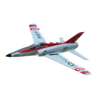
The aft 3-4 inches of the bypass is treated with 3 brushed-
on coats of BVM’s heat shield (#1940). Two 4-40 x ½”
SHCS with washers hold the bypass to CF angle brackets
mounted to F-5.
The P-60/P-70 bypass has a .4” gap between it and the
CF F-5 former. The P-80/P-120 bypass will rest on the
former.
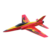
Bolt (2) molded CF mounts using 4-40 bolts and washers. Tap the CF mounts using a 4-40 tap.
For the P-60/70 by-pass; bolt the bottom hole of the CF mount to the top hole of the carbon former.
(2 bolts)
For the P-80/120 Bypass use both holes of the CF mount bolted to the carbon former (4 bolts)
Glue ¼” ply parts are glued to the bottom of the bypass
flanges with AeroPoxy to hold the 4-40 “T” nuts.
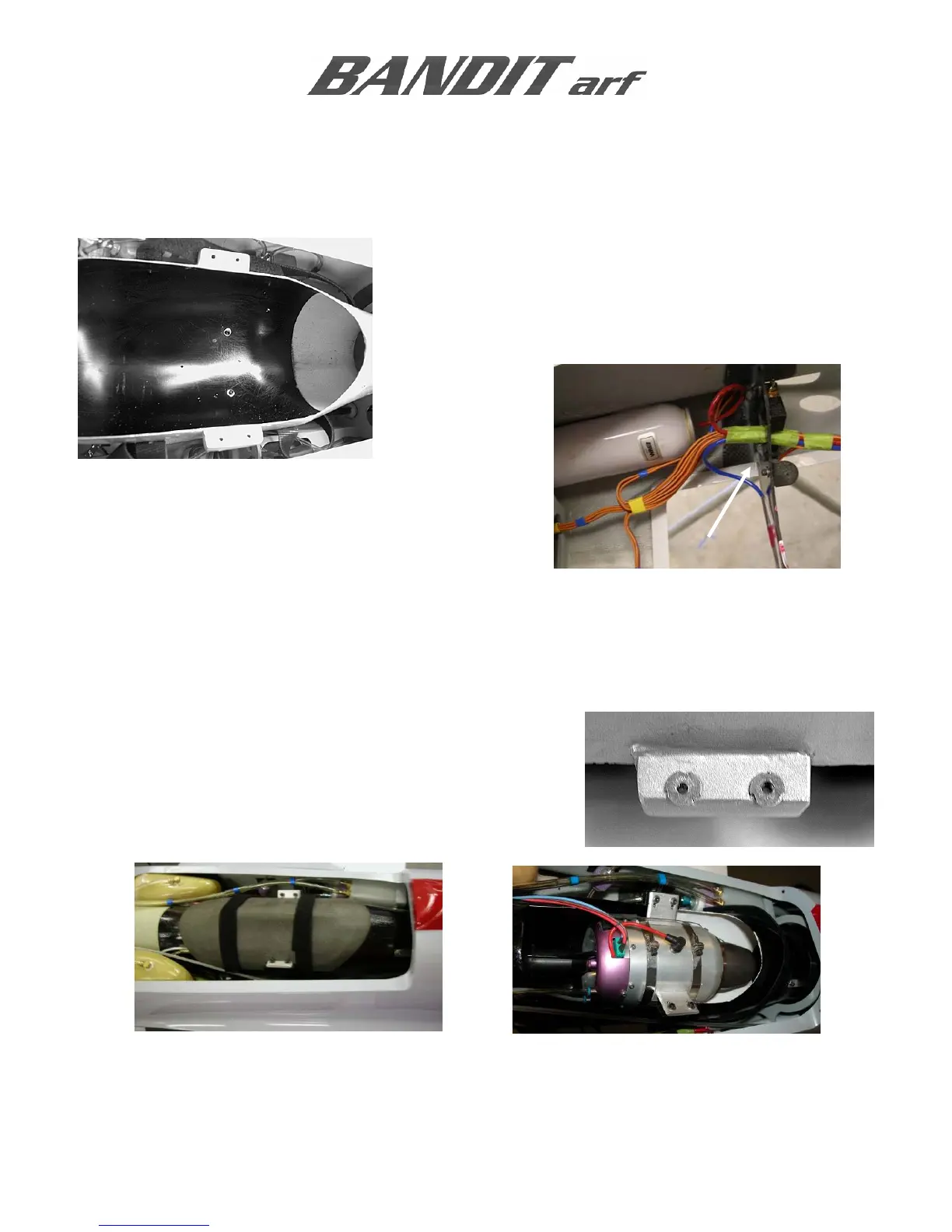
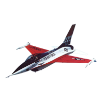
JetCat P-60 is mounted as shown. Note the position of the glow plug. Use a strap around the engine
nozzle to lift it to center of the bypass while tightening the 6-32 screws in the metal straps.