21
EN
6
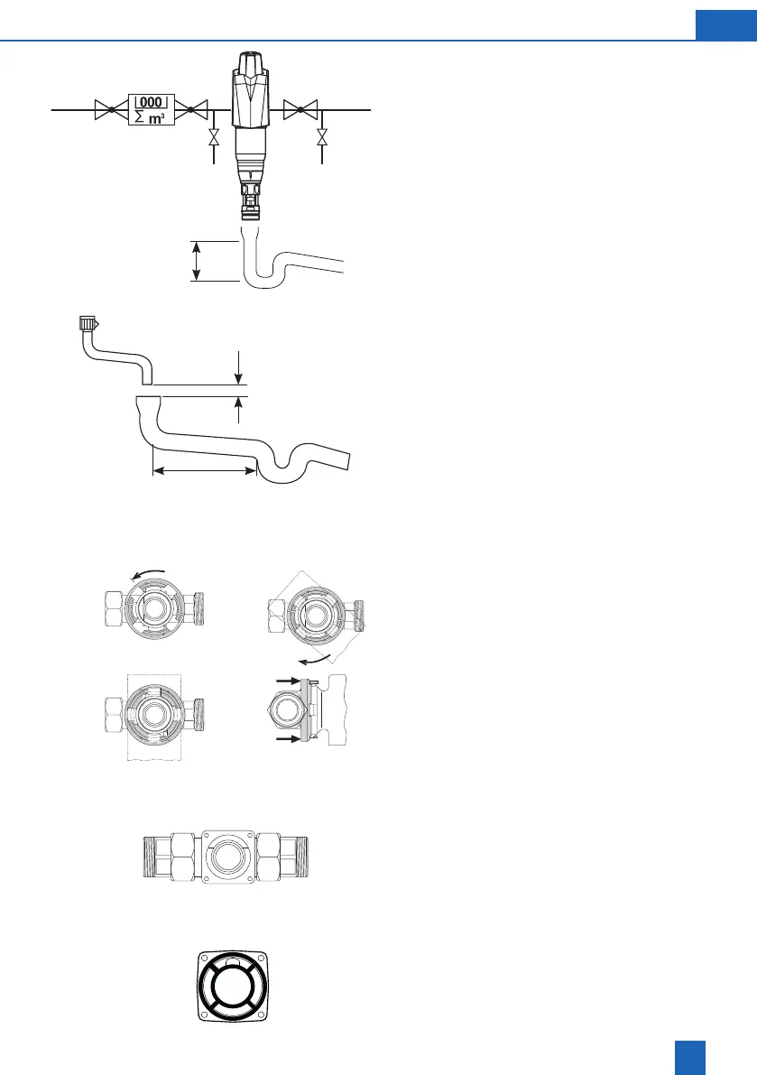
Installthelterinthecoldwaterpipesinfrontofthe
objectstobeprotected(seeinstallationdiagram).
Always provide stop valves.
Install connecting module or connector in the direc-
tionofowinthehorizontalorverticalcoldwater
pipe(observedirectionofowarrow).
Routetheushingwaterconnectiontothedrainso
thatnoreuxoccurs.
Theushingwaterhosemustbesecuredat
a distance of at least 20 mm from the highest
possiblewastewaterlevel(freedischarge).
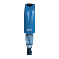
1. Turn the black retaining ring to the left limit stop.
2. Presstheprongsofthedeviceintothespaces
provided
3. Rotate the device clockwise 45° to the limit stop.
4. Pull the black retaining ring with both hands
towards the device until it clicks into place. The
device cannot now be rotated unintentionally.
To release the lter,press the retaining ring
towards the connecting module.
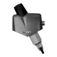
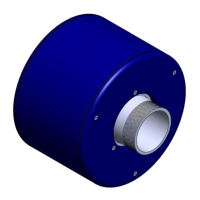
1. Screwtheltertotheconnectorusing4hexa-
gon screws and the seal (screws and washers
included).
2. Checkthesealforpropert.Thefourbarsmust
bepluggedintothelterheadandthesealmust
liecompletelyinthetwogrooves,seegure.
Tighten the screws evenly and crosswise.
> 400 mm
4.
2.1.
3.
min. DN 50
> 20 mm
> 1 m