Rev F Configuration 4-19
4
➤ To install regulator kits
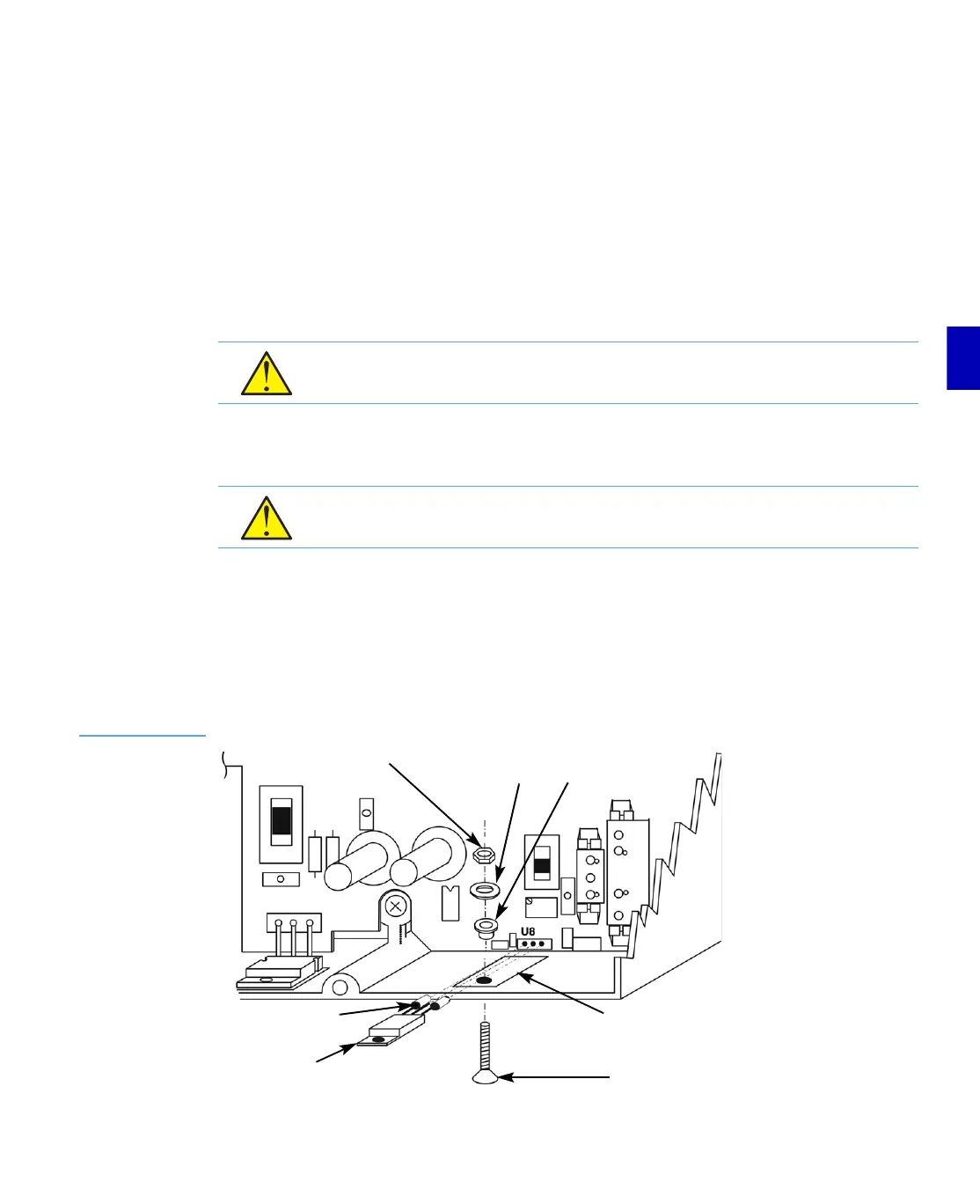
1. Locate the hole in the chassis indicated in Figure 4.8. Place the small insulator pad in the
orientation shown.
2. Ensure that the regulator leads are straight.
3. Place sleeves on the regulator pins as shown in Figure 4.8.
4. Orient the regulator as shown. Insert the regulator pins into the holes labeled U8 until the
regulator mounting screw hole lines up with the hole in the insulator pad and chassis.
5. Insert the binder head Phillips screw from the outside of the RF module as shown in
Figure 4.8. Secure the regulator with the neoprene washer, then the metal washer and nut.
6. Use the #1 Phillips screwdriver to keep the screw from turning while tightening the nut.
Torque to between 4 and 6 in-lbs (.45 and .68N·m).
7. Solder the regulator leads being very careful that the solder does not bridge between leads.
■ If you are upgrading an E729B Line Extender, refer to Installing Diplex Filters (E729B
Only) on page 4-20.
■ If you are not upgrading an E729B Line Extender, refer to Completing the Installation
on page 4-21.
Figure 4.8
Regulator
Installation
CAUTION: Overtightening the regulator mounting screw can short the regulator to the
chassis. Torque to between 4 and 6 in-lbs (.45 and .68N·m).
CAUTION: Solder bridges will short the regulator. Do not allow solder to bridge between
leads.
Nut Metal
Washer
Nylon Shoulder
Washer
Binder Head
Phillips Screw
Regulator
Regulator
Pin Sleeve
Insulator
Pad