Wiring Guidelines (cont’d)
Panel Powered from AutomationDirect PLC via Communications Cable
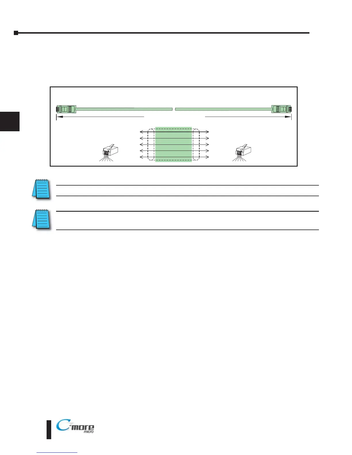
NOTE: Maximum cable length when the panel is powered via a PLC is 10 feet.
NOTE: Only one C-more Micro-Graphic panel can be powered by a CLICK PLC. If a 2nd panel is connected
to a different port on the CLICK PLC, an external power supply is required.
Wiring Guidelines continued at top of the next page.
4–6
Chapter 4: Installation and Wiring
4
Power Supplied to Panel through Cable from CLICK and Direct
Logic PLC RJ12 port:
DL05, DL105, DL205, DL350, DL450, H2 WINPLC
RS 232C (p/n DV 1000CBL)
To PLC
RJ12 Port
To C-more
Micro-Graphic
Serial Port1
6
4
GND
TXD
1
3
GND
Wiring Diagram
3
RXD
2
+5 V
1 = Sig GND
2 = not used
3 = RXD
4 = TXD
5 = +5 VDC
6 = Sig GND
1 2 3 4 5 6
RJ12 6-pin
Phone Plug
(6P6C)
1
GND
6
GND
1 2 3 4 5 6
RJ12 6-pin
Phone Plug
(6P6C)
1 = Sig GND
2 = +5 VDC
3 = RXD
4 = TXD
5 = not used
6 = Sig GND
4
5
RXD
TXD
+5 V
10 feet [3.0 m] Maximum