11
KRISS
3
- TECNA
3
- EVO
3
- ELISE
3
- SHELL
3
- CRISTAL
3
- GLASS - VERVE AT - PRETTY AT - TITANIA AT - VENERE AT - BREEZE AT
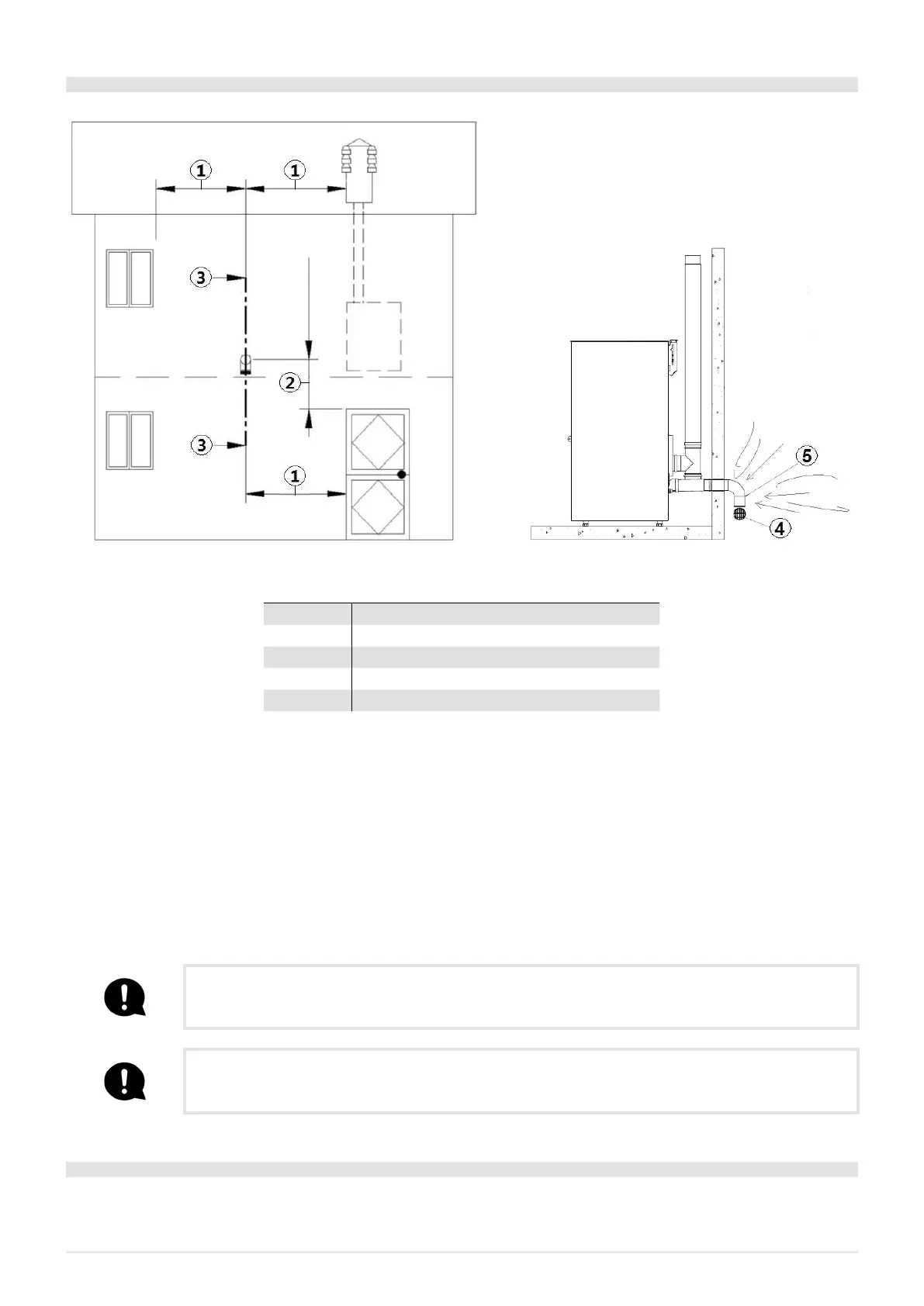
4.2 COMBUSTIBLE AIR INLET FOR SEALEDCHAMBER INSTALLATION
Fig. 11 - Air inlet for sealed-chamber installation
LEGEND Fig. 11
1 ≥ 1,5 mt
2 ≥ 0,3 mt
3-3 Sectional view
4 Shield grid
5 Curve inlet to turn downwards
Check if the purchased stove has a sealed-chamber. If the stove is endowed with a sealed-chamber and you want also the whole
installation with sealed chamber, please read the following instructions:
• It is necessary to extract the air for combustion directly from outside.
• Use a tube with minimum Ø60 mm and maximum 2 meters lenght; to connect see the back of the stove.
• French standards require installation in double-walled flues (concentric system). The combustion air is drawn from the cavity.
• During installation step is necessary to verify the minimum distances required for the combustible air inlet as (for example)
an open door or window causes a vortex which could remove the combustible air necessary to the stove (see the underlying
scheme).
• On the external wall it is necessary to install a curve at 90° to protect the combustible air inflow from wind effects: turn the
curve inlet downwards, see Fig. 11.
• Endow the curve with an external shield grid against birds in such a way that it cannot be obstructed by any object.
Check with your local authorities if exists any restrictive regulation regarding the combustible air inlet: if pre-
sent, they must be applied
In some countries and/or regions the installation with sealed-chamber is obligatory: in case of doubt, please
follow the most restrictive regulations.
4.3 COMBUSTIBLE AIR INLET FOR SEALEDCHAMBER INSTALLATION KRISS
3
TECNO
3
EVO
3
ELI
SE
3
SHELL
3
SHELL
3
PS CRISTAL
3
GLASS VERVE AT PRETTY AT TITANIA AT VENERE AT
How to connect to the stove in the sealed chamber with concentric system: