KRISS
3
- TECNA
3
- EVO
3
- ELISE
3
- SHELL
3
- CRISTAL
3
- GLASS - VERVE AT - PRETTY AT - TITANIA AT - VENERE AT - BREEZE AT
12
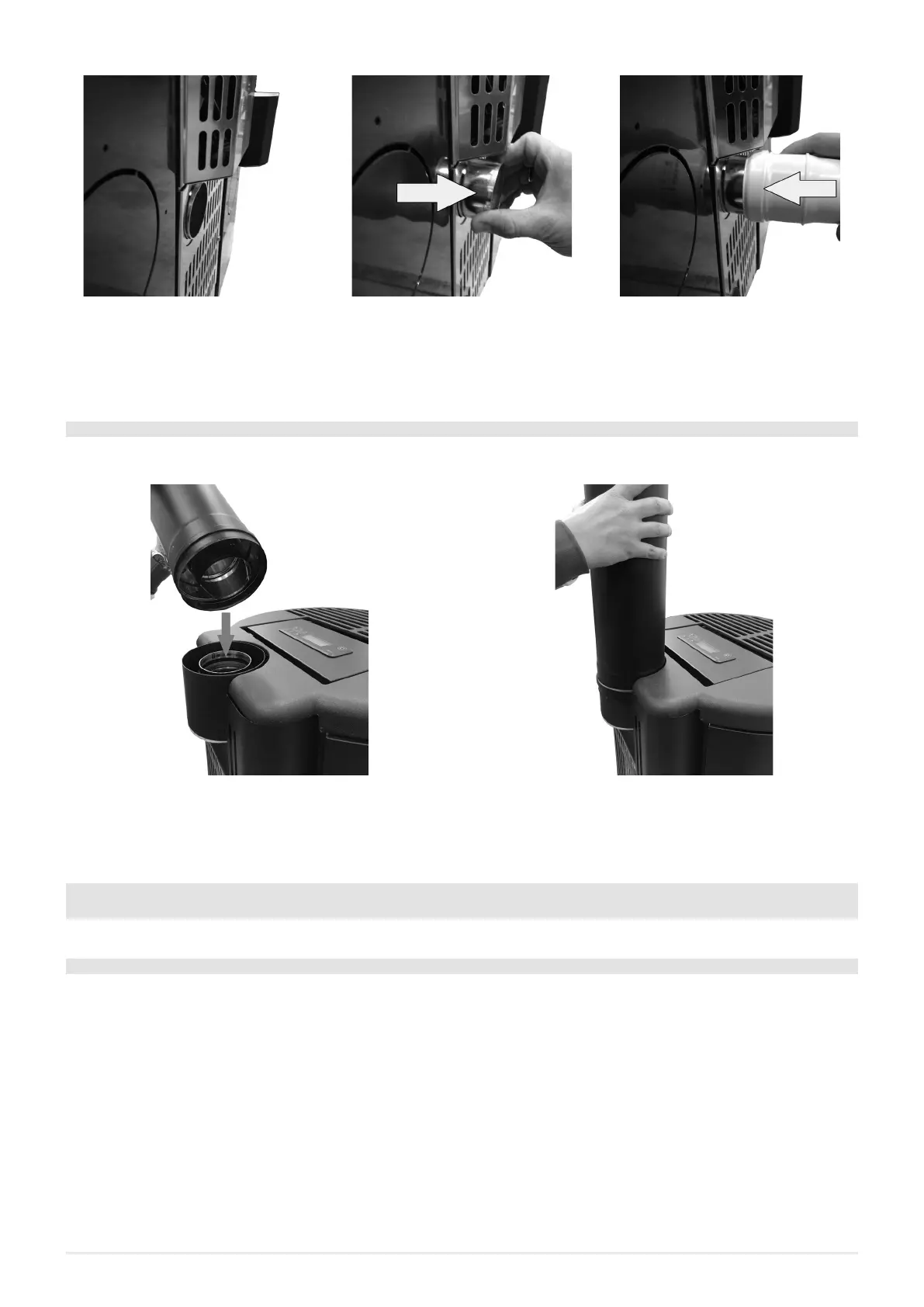
Fig. 12 - Phase1 Fig. 13 - Phase 2 Fig. 14 - Phase 3
• Original position with completely embedded tube (see Fig. 12).
• Pull out the tube for 2 cm (see Fig. 13).
• Insert the female tube ø 6 cm (see Fig. 14).
4.4 COMBUSTIBLE AIR INLET FOR SEALEDCHAMBER INSTALLATION SHELL
3
UP BREEZE AT
How to connect to the stove in the sealed chamber with concentric system:
Fig. 15 - Phase1 Fig. 16 - Phase 2
• Connect the concentric pipe with the fitting located behind the stove (see Fig. 15).
• Push the concentric pipe up to stroke end (see Fig. 16).
5 INSTALLATION
5.1 INTRODUCTION
• The assembly position must be chosen depending on environment, outlet, chimney flue.
• Check with local authorities if there are any restrictive regulations which regard the combustible air inlet, room ventilation,
fume exhaust system together with chimney flue and chimney pot.
• Check if there is the combustible air inlet.
• Check the probable presence of other stoves or appliances which could depress the room.
• Check at switched on stove if there is the presence of CO in the room.
• Check if the chimney has the necessary draught.
• Check if during the fume passage all has been executed in safety (probable fume losses and distances from flammable mate-
rials, etc.…).
• The installation of the appliance must enable an easy access for appliance, fume exhaust pipes and chimney flue cleaning.
• The installation must enable en easy access to the electric connection plug (see ELECTRIC CONNECTION a pag. 30).
• To install more appliances, the external air inlet must be correctly dimensioned (see FEATURES a pag. 40).