M3
...................................................................................................................................................................................
40
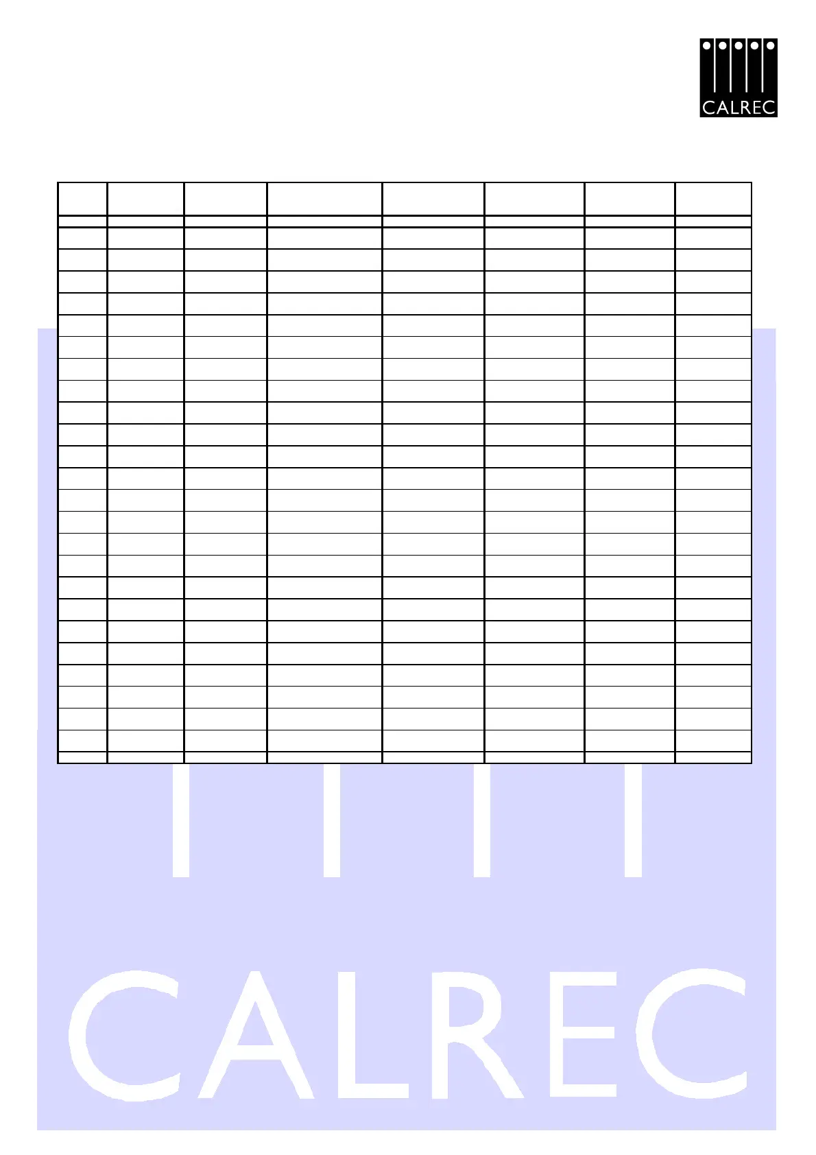
LARGE CHASSIS OUTPUT GUIDE
Connector INS / DIR 1-4 * INS / DIR 13-14** INS / DIR 37-38 MN INS 1&2 ANCILLARY 2 *** ANCILLARY 1 PRINCIPLE O/P'S MONITOR
Type 50F D-TYPE 50F D-TYPE 50F D-TYPE 50F D-TYPE 50F D-TYPE 50F D-TYPE 50F D-TYPE
(Free Male Plug) (Free Male Plug) (Free Male Plug) (Free Male Plug) (Free Male Plug) (Free Male Plug) (Free Male Plug)
PIN No. CIRCUIT CIRCUIT CIRCUIT CIRCUIT CIRCUIT CIRCUIT CIRCUIT
1 . 18
Ch 1 Insert Go
L or M
Ch 13 Insert Go
L or M
Ch 37 or Gp 3 Insert Go
L or M
Ch 1/2 Remote Cut
!
Ch 29/30 Remote Cut
!
Main 1 DESK Output
L
Monitor Bargraph
O/P L
34 . 2
Ch 1 Insert Go
R or nc
Ch 13 Insert Go
R or nc
Ch 37 or Gp 3 Insert Go
R or nc
Ch 3/4 Remote Cut
!
Ch 31/32 Remote Cut
!
Main 1 DESK Output
R
Monitor Bargraph
O/P R
35 . 19
Ch 1 Insert Return
L or M
Ch 13 Insert Return
L or M
Ch 37 or Gp 3 Insert Return
L or M
Ch 5/6 Remote Cut
!
Ch 33/34 Remote Cut
!
Main 1 LINE Output L Talkback O/P
3 . 36
Ch 1 Insert Return
R or nc
Ch 13 Insert Return
R or nc
Ch 37 or Gp 3 Insert Return
R or nc
Ch 7/8 Remote Cut
!
Ch 35/36 or Gp 1/2
Remote Cut
!
Main 1 LINE Output R
SLS External I/P
1L
20 . 4
Ch 1 Direct Output
L or M
Ch 13 Direct Output
L or M
Ch 37 or Gp 3 Direct Output
L or M
Ch 9/10 Remote Cut
!
Ch 37/38 or Gp 3/4
Remote Cut
!
Main 1 LINE Output M
SLS External I/P
1R
37 . 21
Ch 1 Direct Output
R or nc
Ch 13 Direct Output
R or nc
Ch 37 or Gp 3 Direct Output
R or nc
Ch 11/12 Remote Cut
!
CR / CR
Main 2 DESK Output
L
SLS External I/P
2L
5 . 22
Ch 2 Insert Go
L or M
Ch 14 Insert Go
L or M
Ch 38 or Gp 4 Insert Go
L or M
Ch 13/14 Remote Cut
!
Ch 29/30 VCA Control
!
Main 2 DESK Output
R
SLS External I/P
2R
38 . 6
Ch 2 Insert Go
R or nc
Ch 14 Insert Go
R or nc
Ch 38 or Gp 4 Insert Go
R or nc CR / CR
Ch 31/32 VCA Control
!
Main 2 LINE Output L
Monitor LS SEL
O/P L
39 . 23
Ch 2 Insert Return
L or M
Ch 14 Insert Return
L or M
Ch 38 or Gp 4 Insert Return
L or M
Ch 1/2 VCA Control
!
Ch 33/34 VCA Control
!
Main 2 LINE Output R
Monitor LS SEL
O/P R
7 . 24
Ch 2 Insert Return
R or nc
Ch 14 Insert Return
R or nc
Ch 38 or Gp 4 Insert Return
R or nc
Ch 3/4 VCA Control
!
Ch 35/36 or Gp 1/2 VCA
Control
!
Main 2 LINE Output M RTB I/P
40 . 8
Ch 2 Direct Output
L or M
Ch 14 Direct Output
L or M
Ch 38 or Gp 4 Direct Output
L or M
Ch 5/6 VCA Control
!
Ch 37/38 or Gp 3/4 VCA
Control
!
RTB Enable
!
/
0L
41 . 25
Ch 2 Direct Output
R or nc
Ch 14 Direct Output
R or nc
Ch 38 or Gp 4 Direct Output
R or nc
Ch 7/8 VCA Control
!
CR / CR
Mix Minus
External I/P
9 . 26
Ch 3 Insert Go
L or M Main 1 Insert Go L
Ch 9/10 VCA Control
!
Ch 29/30 Fader Start
!
Monitor LS Output L
Mix Minus
External O/P
42 . 10
Ch 3 Insert Go
R or nc Main 1 Insert Go R
Ch 11/12 VCA Control
!
Ch 31/32 Fader Start
!
Monitor LS Output R CR / CR
43 . 27
Ch 3 Insert Return
L or M Main 1 Insert Ret L
Ch 13/14 VCA Control
!
Ch 33/34 Fader Start
!
Headphone Output L
External Talkback
O/P 1
11 . 28
Ch 3 Insert Return
R or nc Main 1 Insert Ret R CR / CR
Ch 35/36 or Gp 1/2
Fader Start
!
Headphone Output R
External Talkback
O/P 2
44 . 12
Ch 3 Direct Output
L or M
Ch 1/2 Fader Start
!
Ch 37/38 or Gp 3/4
Fader Start
!
PFL LS Output
Monitor LS I/P
A1L
45 . 29
Ch 3 Direct Output
R or nc
Ch 3/4 Fader Start
!
CR / CR Aux 1 Output M
Monitor LS I/P
A1R
13 . 46
Ch 4 Insert Go
L or M Main 2 Insert Go L
Ch 5/6 Fader Start
!
ON-AIR relay com/no Aux 2 Output M
Monitor LS I/P
A2L
30 . 14
Ch 4 Insert Go
R or nc Main 2 Insert Go R
Ch 7/8 Fader Start
!
Tx 'E' / 0L Aux 3 Output M
Monitor LS I/P
A2R
47 . 31
Ch 4 Insert Return
L or M Main 2 Insert Ret L
Ch 9/10 Fader Start
!
Tone
!
/ TB
!
Aux 4 Output L
Monitor LS I/P
A3L
15 . 48
Ch 4 Insert Return
R or nc Main 2 Insert Ret R
Ch 11/12 Fader Start
!
AFL / PFL Aux 4 Output R
Monitor LS I/P
A3R
32 . 16
Ch 4 Direct Output
L or M Studio LS EXT CUT / 0L
Ch 13/14 Fader Start
!
SLS Bus
!
/ -
Studio LS Output L
Monitor LS I/P
A4L
49 . 33
Ch 4 Direct Output
R or nc Monitor LS EXT CUT / 0L CR / CR External Tone Output Studio LS Output R
Monitor LS I/P
A4R
17 . 50
Chassis Chassis Chassis Chassis Chassis Chassis Chassis
* INS / DIR 1-4 also applies to circuits in connectors INS/DIR 5-8, INS/DIR 9-12, INS/DIR 15-18, INS/DIR
19-22, INS/DIR 23-26, INS/DIR 29-32,
INS/DIR 33-36 respectively (INS/DIR 33-36 may also contain Group circuits in slots 35-36)
** INS / DIR 13-14 also applies to circuits in connector INS/DIR 27-28 respectively
*** ANCILLIARY 2 also applies to circuits shown in the ANC 3 connector (ANC 3 covers channels 15-28)
nc = not connected, if for example the mono PQ5122 or mono XL5125 is fitted
All Enable & Logic !"lines are active low and are pulled down to 0L when activated or to activate.
All cable screens should be connected to chassis.
CR (Centre Rail) is a clean audio earth reference & is provided for earth reference for unbalanced circuits only
and should not be used as a general cable screen.
All VCA lines should be terminated to CR when not used.
0L (0 Volts logic earth for DC switching)
L .R are the Left & Right signals of a stereo output.
M is the mono output.