Home
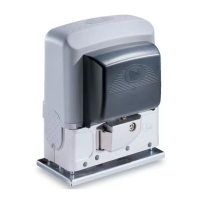
CAME
Gate Opener
BK Series
CAME BK Series Installation Manual
5
of 1
of 1 rating
28 pages
Give review
Manual
Specs
To Next Page
To Next Page
To Previous Page
To Previous Page
Loading...
p.
9
- Manual
FA
01
2
9
2-
EN
- 1
2/20
1
8 - © C
AM
E S.p.
A
. - T
he co
ntents of this manual ma
y c
hange, at an
y time, and without notice. - Original inst
ructions
Remove the foundation frame and fill the hole with earth around the concrete blo
ck.
Remove the nuts from the bolt
s.
Fit the electric ca
bles into the tubes
so that they come out about 6
00 mm.
8
10
Table of Contents
Description of Parts
6
Standard Installation
6
Preliminary Checks
7
Fastening the Operator
12
Establishing the Limit-Switch Points
12
Control Board
13
Electrical Connections
14
Power Supply
15
Control Devices
16
Safety Devices
17
Description of the Commands
19
Functions Menu
19
Travel Calibration
22
Managing Users
23
Error Messages
24
Final Operations
25
Dismantling and Disposal
26
Disposing of the Packaging
26
Other manuals for CAME BK Series
Installation, Operation And Maintenance Manual
112 pages
Manual
18 pages
5
Based on 1 rating
Ask a question
Give review
Questions and Answers:
Need help?
Do you have a question about the CAME BK Series and is the answer not in the manual?
Ask a question
CAME BK Series Specifications
General
Motor Voltage
230 V AC
Operating Temperature
-20°C to +55°C
Power Supply
230V AC
Motor Power
300W
Limit Switch Type
Mechanical
Safety Features
Obstacle detection
Related product manuals
CAME BK 800
22 pages
CAME BK-BKE
24 pages
CAME BK-221E
24 pages
CAME BK 1200
22 pages
CAME BK 1800
22 pages
CAME BK 2200
22 pages
CAME BX241
20 pages
CAME BXE 24
20 pages
CAME BX704AGS
32 pages
CAME BXL04AGS
96 pages
CAME BXV04AGS
32 pages
CAME BX604AGS
84 pages