9
2.2 - Wiring the Motor
THE FROG MOTOR ALWAYS COMES PREWIRED AND THE CONNECTIONS TO
THE MOTOR SHOULD BE MADE IN THE JUNCTION BOXES AT THE BASE OF
THE GATE POST (I.E OUT OF THE GROUND OR FOUNDATION CASING) AS
SHOWN IN FIG 3.
UNDER NO CIRCUMSTANCES MUST THE MOTOR BE DISCONNECTED FROM
THE GEARBOX AS THIS WILL INVALIDATE THE WARRANTY.
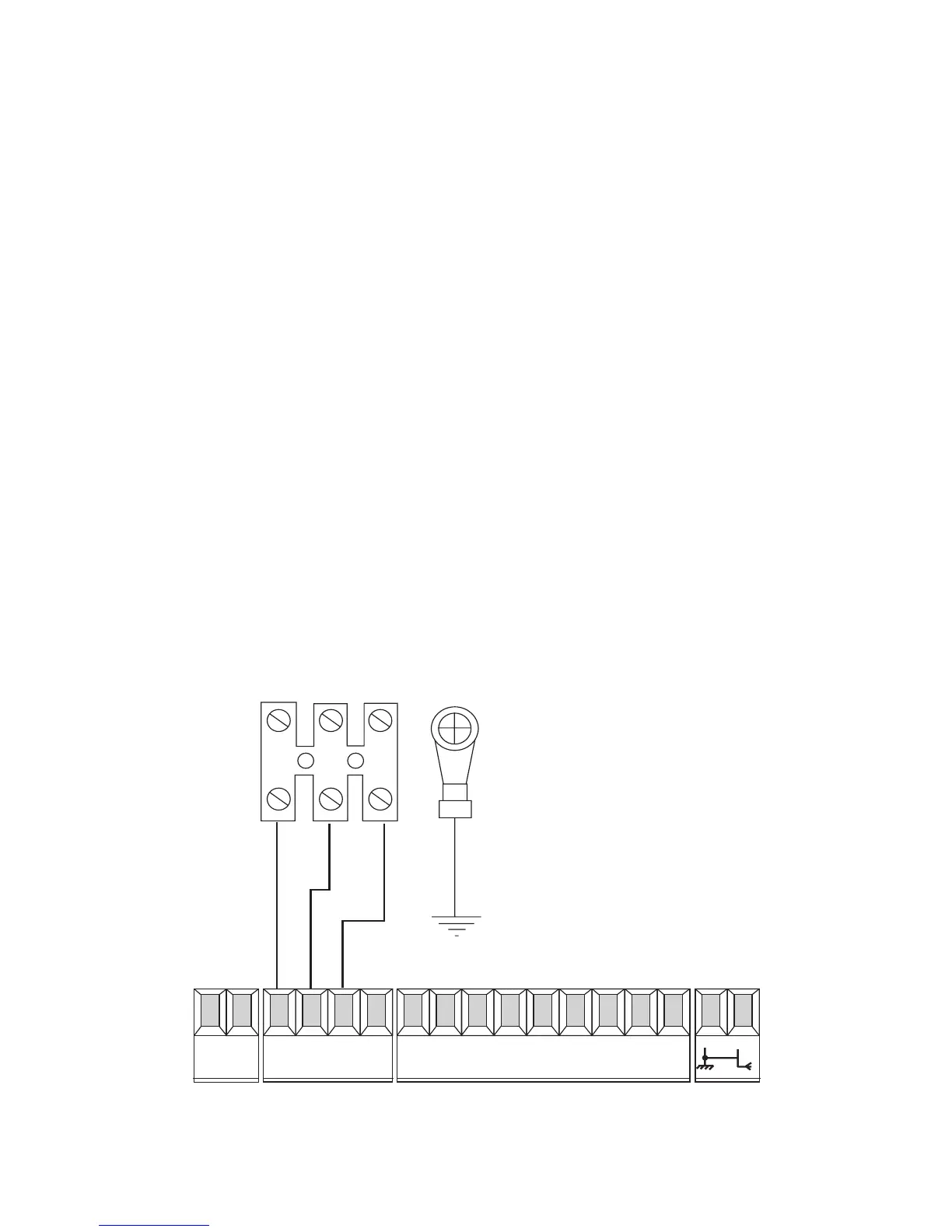
WHEN CONNECTING THE MOTOR TO THE CONTROL PANEL THE BLUE WIRE
ON THE MOTOR IS THE COMMON WIRE AND IS ALWAYS TO THE “W” ON
THE TERMINAL STRIP IN THE CONTROL PANEL. THE BROWN AND BLACK
WIRES ARE THE MOTOR DIRECTIONS AND ARE CONNECTED TO “X+Y” FOR
MOTOR 2. MOTOR 2 IS ALWAYS USED FOR SINGLE GATE
INSTALLATIONS.
ENSURE THAT THE MOTOR IS ADEQUATELY EARTHED.
Fig 7
U V W
MOTOR
EARTH
L1 L2 U V W E1 ES 10 11 1 2 3 5 7 C1

 Loading...


