EasyManuals Logo

CAME FROG series Installation Instructions

CAME FROG series
32 pages
To Next Page IconTo Next Page
To Previous Page IconTo Previous Page
Page #14 background imageLoading...
Page #14 background image
STAGE 3
COMMISSIONING THE CONTROL PANEL
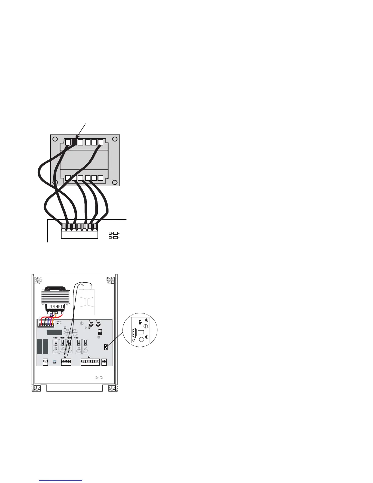
3.1 - Initial Wiring & Control Panel Setup
13
1. CONNECT POWER TERMINALS L1 - L2
AND A SUITABLE EARTH (L2 BEING LIVE!)
2. SELECT THE MOTOR POWER SETTING ON
THE TRANSFORMER TO LEVEL 1 FOR
COMMISSIONING
Fig 12
3. INSERT THE ‘START-UP’ CAPACITOR INTO
THE CONTROL PANEL. THE TWO BLACK
WIRES SHOULD BE CONNECTED TO THE
CAPACITOR.
4. ENSURE THAT THE MOTORS ARE
ADEQUATELY EARTHED
ZA4
Fig 13

Other manuals for CAME FROG series

Questions and Answers:

Question and Answer IconNeed help?

Do you have a question about the CAME FROG series and is the answer not in the manual?

CAME FROG series Specifications

General IconGeneral
Motor Voltage24 V DC
Max Gate Weight800 kg
Duty Cycle30%
Limit SwitchYes
Power Supply230 V AC
Safety FeaturesObstacle detection
TypeElectromechanical underground gate opener

Related product manuals