EasyManuals Logo

CAME FROG series Installation Instructions

CAME FROG series
32 pages
To Next Page IconTo Next Page
To Previous Page IconTo Previous Page
Page #11 background imageLoading...
Page #11 background image
10
ZA4
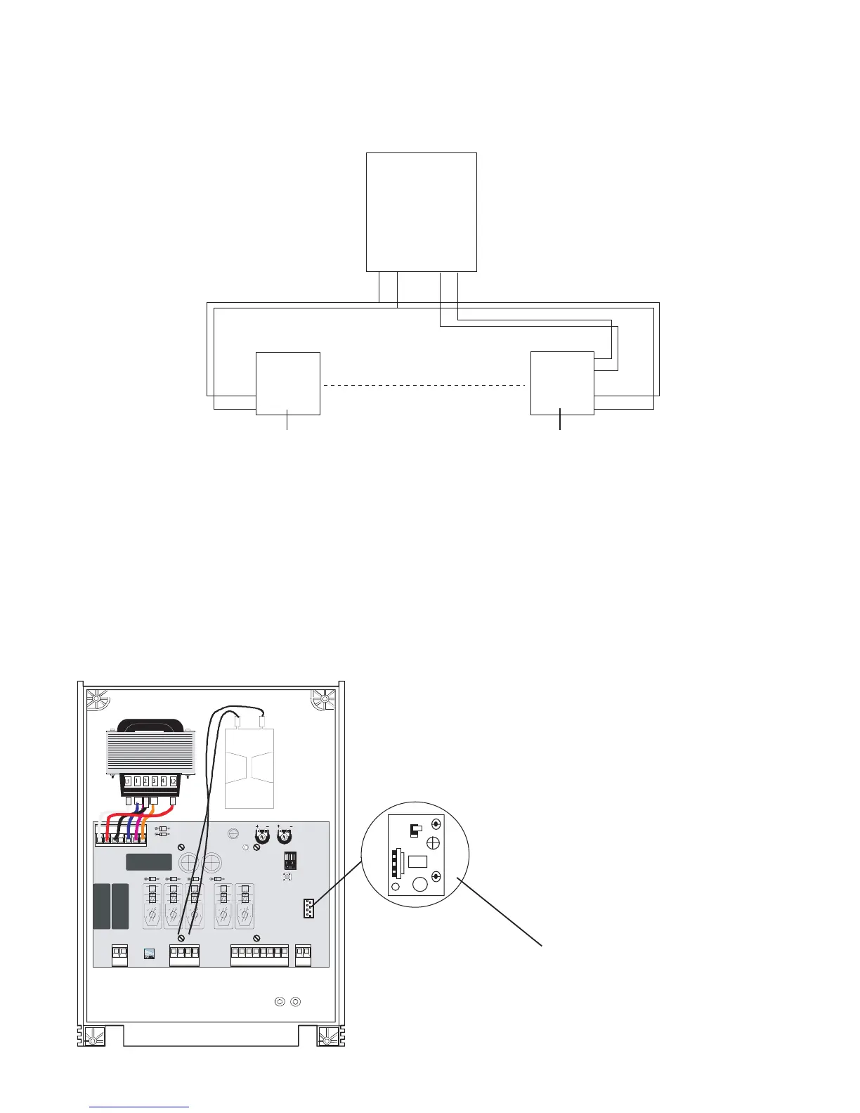
2.3 - Wiring in the Safety Photocells
SAFETY BEAMS SHOULD BE FITTED APPROXIMATELY
15 INCHES FROM GROUND LEVEL
CONTROL PANEL
10 11 2 C1
C
NC
RX
10
11
TX
10
11
Fig 8
SAFETY
BEAM
RECEIVER
SAFETY
BEAM
TRANSMITTER
IF FITTING A SECOND ARC LINE OF SAFETY BEAMS THEN C & NC MUST BE WIRED IN “SERIES”
2.4 - Inserting the Radio Frequency Card
INSERT THE RADIO FREQUENCY
CARD INTO THE SMALL SOCKET
ON THE CONTROL PANEL
(ENSURE THAT THE POWER IS
TURNED OFF TO THE CONTROL
PANEL BEFORE INSERTING THE
FREQUENCY CARD)
ANTENNA
WIRING
POINT
Fig 9
NC
C

Other manuals for CAME FROG series

Questions and Answers:

Question and Answer IconNeed help?

Do you have a question about the CAME FROG series and is the answer not in the manual?

CAME FROG series Specifications

General IconGeneral
Motor Voltage24 V DC
Max Gate Weight800 kg
Duty Cycle30%
Limit SwitchYes
Power Supply230 V AC
Safety FeaturesObstacle detection
TypeElectromechanical underground gate opener

Related product manuals