EasyManuals Logo

CAME FROG series Installation Instructions

CAME FROG series
32 pages
To Next Page IconTo Next Page
To Previous Page IconTo Previous Page
Page #12 background imageLoading...
Page #12 background image
2.5 - Wiring in the Tuned Antenna
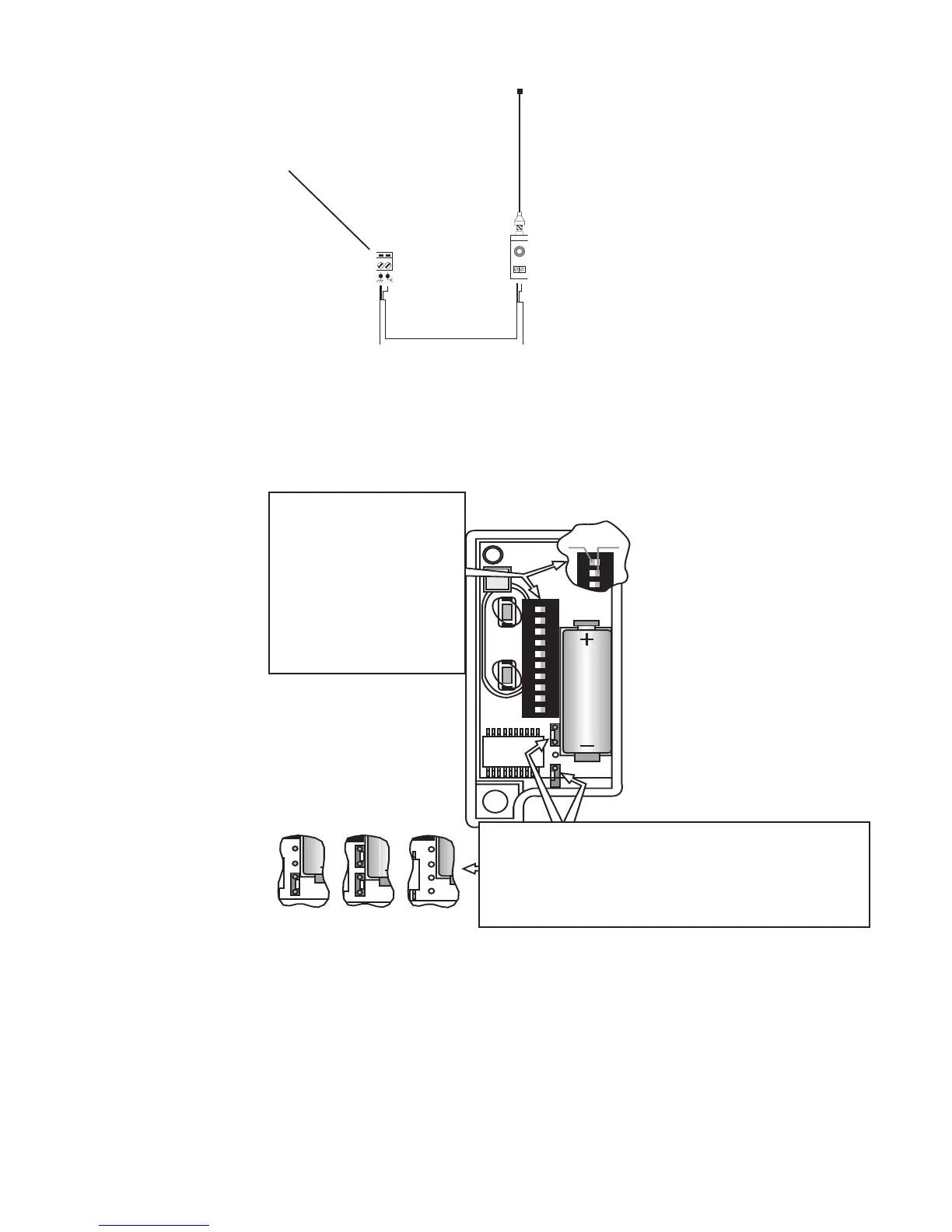
2.6 - Coding the Remote Controls
1. REMOVE THE BATTERY COVER & CASING OF THE REMOTE CONTROL
HANDSET TO REVEAL THE DIAGRAM BELOW
2.7 - Powering up the Control Panel
CONNECT PROTECTED MAINS POWER TO TERMINALS L1 + L2 IN THE
CONTROL PANEL (L2 BEING LIVE!). ENSURE THAT THE CONTROL PANEL
IS ADEQUATELY EARTHED.
ANTENNA
WIRING
POINT
Fig 10
Bat
Battery 12V
ON
1 2 3 4 5 6 7 8 9 10
8 9 10
ON OFF
Bt
Batt
1
2. SET THE BANK OF
DIPSWITCHES ON
ALL REMOTES TO
EXACTLY THE SAME
CODE OF YOUR
CHOICE.
3. UNLESS PROGRAMMING FOR GATES AND
GARAGE DOORS TO OPEN BY REMOTE
CONTROL FROM THE SAME HANDSET ENSURE
THAT THE JUMPER STRAPS SHOWN HERE ARE
IN THE SAME POSITIONS ON ALL REMOTES
Fig 11
11

Other manuals for CAME FROG series

Questions and Answers:

Question and Answer IconNeed help?

Do you have a question about the CAME FROG series and is the answer not in the manual?

CAME FROG series Specifications

General IconGeneral
Motor Voltage24 V DC
Max Gate Weight800 kg
Duty Cycle30%
Limit SwitchYes
Power Supply230 V AC
Safety FeaturesObstacle detection
TypeElectromechanical underground gate opener

Related product manuals