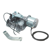
INSTALLATION INSTRUCTIONS
CONTENTS
1) Stage 1:- Civil & Mechanical Section Page
1.1 INSTALLATION OF THE FOUNDATION 3
1.2 BASIC CABLE LAYOUT 4
1.3 LOW VOLTAGE CABLE LAYOUT 4
1.4 INSTALLING THE MOTOR 5
1.5 HANGING THE GATE 5
1.6 FITTING THE GATE LOCK 6
2) Stage 2:- Wiring & Electrical
2.1 FITTING THE CONTROL PANEL IN THE CASING 8
2.2 WIRING THE MOTOR 9
2.3 WIRING IN THE SAFETY PHOTOCELLS 10
2.4 INSERTING THE RADIO FREQUENCY CARD 10
2.5 WIRING IN THE TUNED ANTENNA 11
2.6 CODING THE REMOTE CONTROLS 11
2.7 POWERING UP THE CONTROL PANEL 11
3) Stage 3:- Commissioning the Control Panel
3.1 INITIAL WIRING & CONTROL PANEL SETUP 13
3.2 OPENING & CLOSING THE GATE 14
3.3 CONTROL PANEL ADJUSTMENTS 15
3.4 AUTOMATIC CLOSE & SAFETY PHOTOCELLS 16
3.5 PROGRAMMING THE REMOTE CONTROLS TO THE
CONTROL PANEL 17
4) Troubleshooting Guide 19
5) Technical Information 20
5.1 TECHNICAL SPECIFICATIONS 21
5.2 CASING DIMENSIONS 21
5.3 OPERATING LIMITS 21
5.4 MOTOR TORQUE SETTINGS 22
5.5 ZA5 CONTROL PANEL DESCRIPTION 23
5.6 ZA5 WIRING DIAGRAM 25
5.7 CONTROL PANEL ADJUSTMENTS 26
5.8 ELECTRICAL CONNECTIONS 27
5.9 DIPSWITCH FUNCTIONS 29
5.10 RE-HANDING THE MOTOR 30
6) Contact Information
“TIME MARCHES ON BUT CAME AUTOMATION EQUIPMENT STANDS THE TEST OF TIME...”

 Loading...