Terminals: SE terminals 1-16
Accuracy: ±(0.01% of measurement + resolution), where resolution is 0.13 µs divided by the
number of cycles to be measured
Ranges:
l Minimum signal centered around specified period average threshold.
l Maximum signal centered around datalogger ground.
l Maximum frequency = 1/(2 * (minimum pulse width)) for 50% duty cycle signals
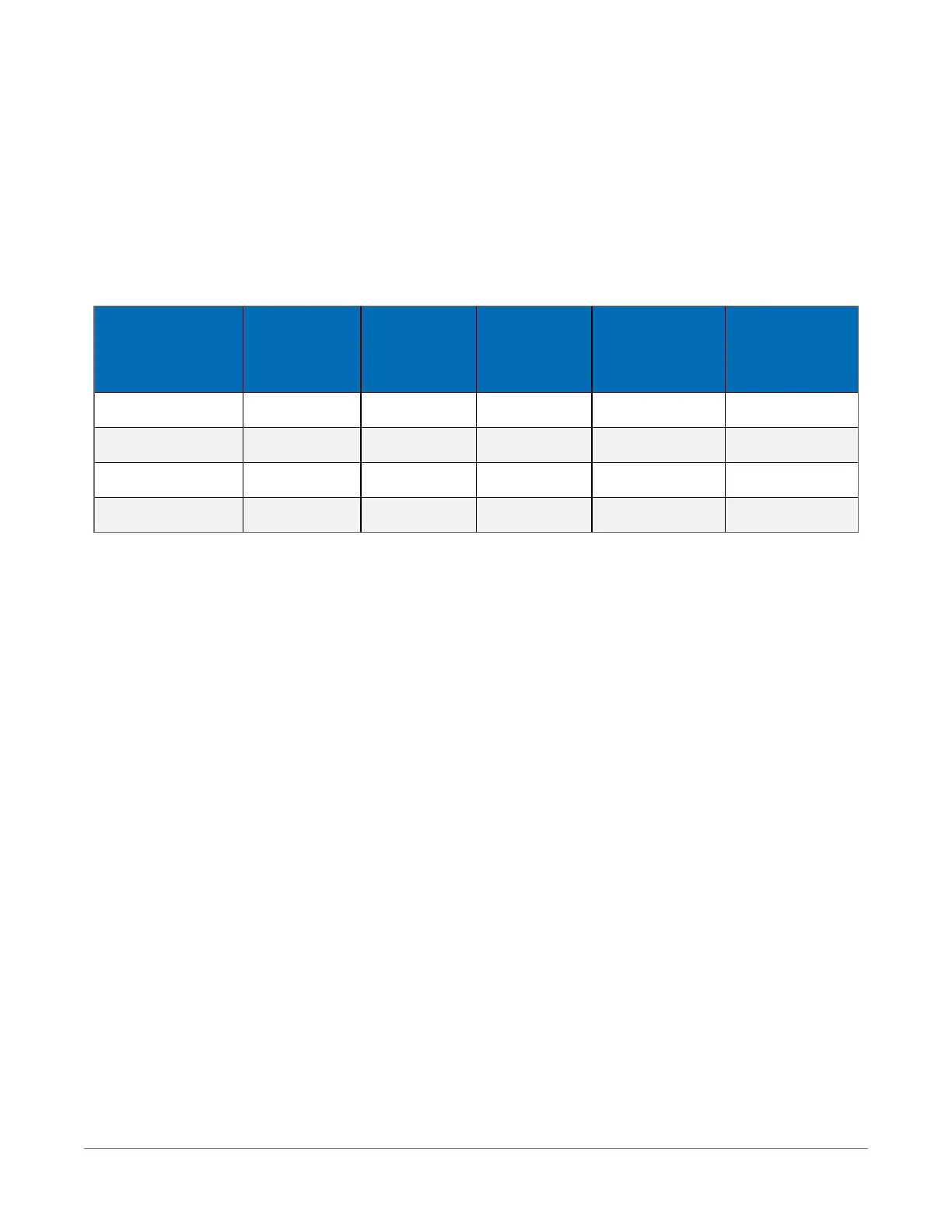
Gain Code
Option
VoltageGain
Minimum
PeaktoPeak
Signal (mV)
Maximum
PeaktoPeak
Signal (V)
Minimum
PulseWidth
(µs)
Maximum
Frequency
(kHz)
0 1 500 10 2.5 200
1 2.5 50 2 10 50
2 12.5 10 2 62 8
3 64 2 2 100 5
See also Period-averaging measurements (p. 70).
10.5.4 Current-loop measurement specifications
The datalogger makes current-loop measurements by measuring across a current-sense resistor
associated with the RS-485 resistive ground terminals RG1 & RG2.
Maximum Input Voltage: ±16 V
Resistance to Ground: 101 Ω
Current Measurement Shunt Resistance: 10 Ω
Maximum Current Measurement Range: ±80 mA
Absolute Maximum Current: ±160 mA
Resolution: ≤ 20 nA
Accuracy: ±(0.1% of reading + 100 nA) @ -40 to 70 °C
See also Current-loop measurements (p. 61).
10.6 Pulse measurement specifications
Two inputs (P1-P2) individually configurable for switch closure, high-frequency pulse, or low-
level AC measurements. See also Digital input/output specifications (p. 171). Each terminal has its
10. Specifications 169

 Loading...


