() instructions. Other functions include device-driven interrupts, asynchronous
communications and SDI-12 communications. The high voltage for these terminals defaults
to 5 V, but it can be changed to 3.3 V using the PortPairConfig() instruction.
Terminals C4, C5, and C7 can also be configured for pulse width modulation with a
maximum period of 36.4 s. A C terminal configured for digital I/O is normally used to
operate an external relay-driver circuit because the terminal itself has limited drive capacity.
l VX terminals can be set low or high using the PortSet() or SWVX() instruction. For
more information on these instructions, see the CRBasic help.
l SW12 terminals can be set low (0 V) or high (12 V) using the SW12() instruction.
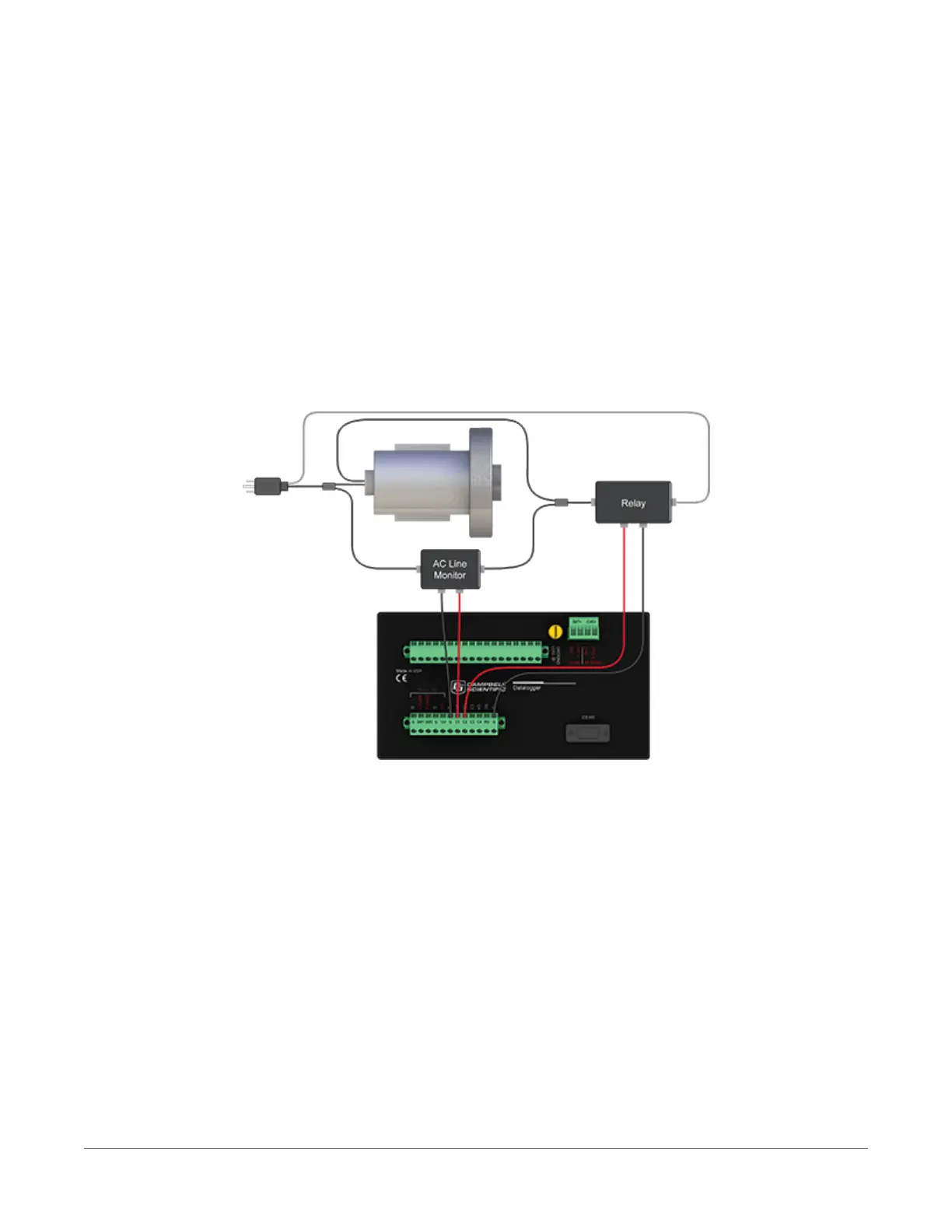
The following image illustrates a simple application wherein a C terminal configured for digital
input, and another configured for control output are used to control a device (turn it on or off)
and monitor the state of the device (whether the device is on or off).
In the case of a cell modem, control is based on time. The modem requires 12 Vdc power, so
connect its power wire to a datalogger SW12 terminal. The following code snip turns the modem
on for the first ten minutes of every hour using the TimeIsBetween() instruction embedded
in an If/Then logic statement:
If TimeIsBetween (0,10,60,Min)Then
SW12(SW12_1,1,1) 'Turn phone on.
Else
SW12(SW12_1,0,1) 'Turn phone off.
EndIf
2. Wiring panel and terminal functions 15

 Loading...


