Chapter 4
4-3
4.1.5 Control System Configuration (iR2020/iR2020J/iR2020i)
0010-4244
iR2020 / / iR2020i
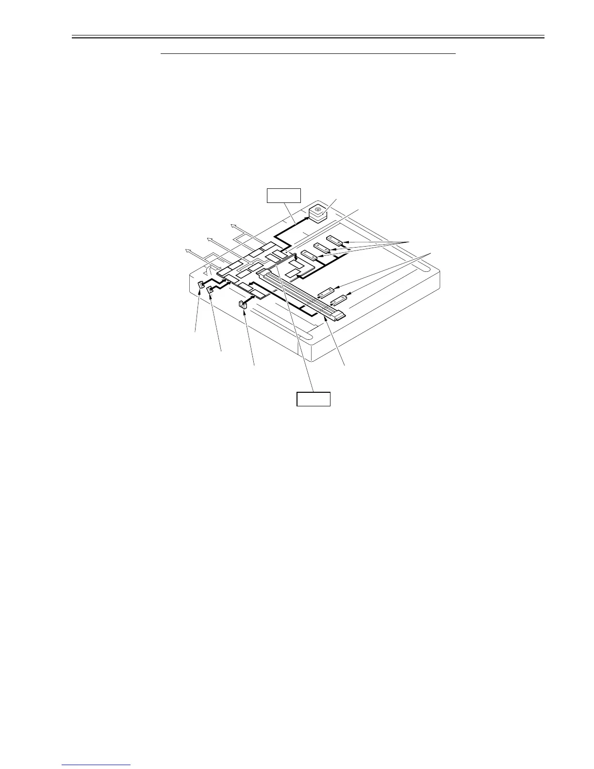
The control system configuration of the original exposure system is shown below.
F-4-3
[1] Printer main body (Connected to the image processor PCB)
[2] Connected to ADF
[3] Connected to the power supply PCB
[4] Reader motor drive control
[5] Reader motor (M401)
[6] Reader controller PCB
[7] Original sensor (horizontal scan direction)
[8] Original sensor (vertical scan direction)
[9] Contact image sensor
[10] Image signal
[11] CISHP sensor (PS503)
[12] Copyboard cover open/close sensor (Front: SR403)
[13] Copyboard cover open/close sensor (Front: SR402)
4.1.6 Control System Configuration (iR2016/iR2016J/iR2016i)
0012-6045
iR2016J / iR2016 / iR2016i
The control system configuration of the original exposure system is shown below.
[2] Reader controller PCB - Controls drive of the reader unit and image processing.
[3] Reader motor M401 Pulse motor: Controls drive of the carriage.
[4] Reader heater*1 - Prevents condensation inside the original glass.
[5] Contact image sensor (CIS) - Uses LEDs for indirect exposure (LED +
Photoconductor)
[6] CISHP sensor SR401 Photo interrupter: Detects the CIS position.
[7] Copyboard cover open/close
sensor
SR403 Finishes detecting the original size when the
copyboard cover angle is 5 deg.
*1 Option setting
Component No. Function/Specification
J404
J403
J412
J411
J407
J401
J402
J408
J409
J410
J405
J413
J406
[5]
[13]
[12]
[11]
[7]
[8]
[2]
[1]
[3]
[10]
[4]
[6]
[9]
 Loading...