Chapter 9
9-3
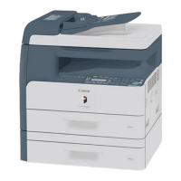
Fan Control Sequence
F-9-6
E805-0000 (Main body fan error)
When the cooling fan of the main body starts, the fan lock detection signal (FAN_LOCK) has been held at the "H" level for longer than the prescribed time.
9.3 Power Supply System
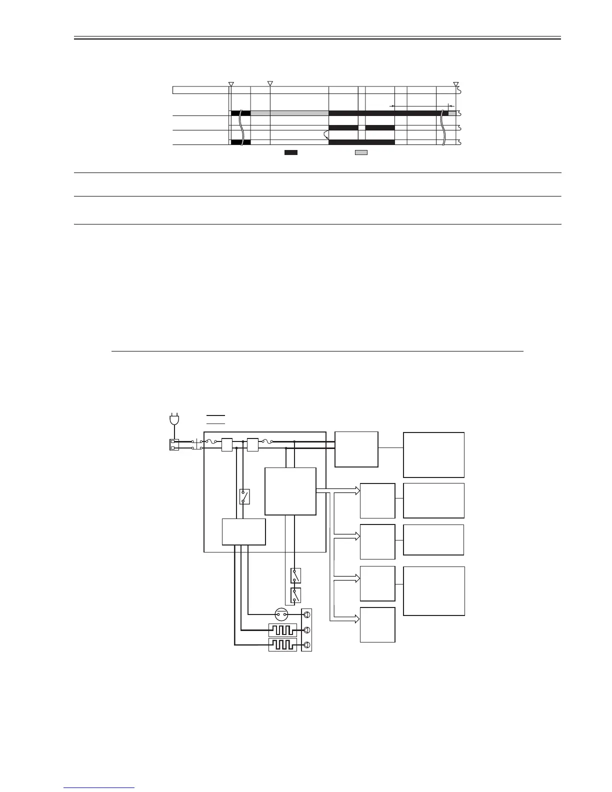
9.3.1 Power Supply
9.3.1.1 Outline (iR2020/iR2020J/iR2016/iR2016J)
0011-2193
iR2016J / iR2016 / iR2020 /
When the main power switch (SW1) is turned on, AC power is supplied to the low-voltage power supply circuit in the power supply PCB.
The low-voltage power supply circuit supplies +3.3 V, +5 V, and +24 V to operate the machine.
+24 V is supplied to the motors, fan, electromagnetic clutch, solenoid, etc. +5 V and +3.3 V are supplied to the sensor, etc.
There are two types of +24 V voltages: +24 V which is normaly supplied from the low voltage power supply and +24 VR which is cut off when the front cover or
the left door is opened. The +24 VR also plays the role of a door open detection signal (DOPEN). This signal allows the CPU to detect that the front cover or the
left door has opened.
T-9-1
F-9-7
9.3.1.2 Outline (iR2020i/iR2016i)
0012-6362
iR2016i / iR2020i
When the main power switch (SW1) is turned on, AC power is supplied to the low-voltage power supply circuit in the power supply PCB.
The low-voltage power supply circuit supplies +3.3 V, +5 V, and +24 V to operate the machine.
+24 V is supplied to the motors, fan, electromagnetic clutch, solenoid, etc. +5 V and +3.3 V are supplied to the sensor, etc.
There are two types of +24 V voltages: +24 V which is normaly supplied from the low voltage power supply and +24 VR which is cut off when the front cover or
the left door is opened. The +24 VR also plays the role of a door open detection signal (DOPEN). This signal allows the CPU to detect that the front cover or the
Part Name Function
Power supply PCB Generates DC power from AC power.
Option power supply PCB (option) Generates DC power from AC power for the options.
Main power switch (SW1) Supplies AC power to the power supply PCB.
Front cover switch (SW2) Detects opening/closing of the front cover and cuts off +24 VR.
Left door switch (SW3) Detects opening/closing of the left door and cuts off +24 VR.
INTR STBY WMUPR
: Half speed (+16V): Full speed (+24V)
PRINT PRINT LSTR
30sec
STBY
Heat Discharge Fan
(FM1)
Registration sensor
(SR209)
Fixing Drive Motor
(M201)
Power switch ON/
Going out of sleep mode
Copy start key ON
Power switch OFF
 Loading...