Chapter 11
11-1
11.1 Scanning System
11.1.1 Procedure after Replacing the CIS (iR2020/
iR2020J/iR2016/iR2016J)
0011-2391
iR2016J / iR2016 / iR2020 /
After replacing the contact image sensor (CIS), go through the following
steps to perform inter-channel output correction:
1) Enter the service mode.
Sequentially press the User Mode key " ", 2 key, 8 key, and User Mode
key " " on the operation panel.
2) Using the arrow keys on the operation panel, display "TEST MODE".
3) Press the OK key.
4) Press the 2 key. "SCAN TEST" appears.
5) Press the 1 key.
After completion of the above steps, contact sensor output correction will be
performed and parameters will be set automatically.
11.1.2 Procedure after Replacing the CIS (iR2020i/
iR2016i)
0012-6059
iR2016i / iR2020i
After replacing the contact image sensor (CIS), go through the following
steps to perform inter-channel output correction:
1) Enter the service mode.
Sequentially press the Additional functions key, 2 key, 8 key, and Additional
functions key on the operation panel.
2) Press the arrow key on the touch panel to display "TEST MODE".
3) Press [OK].
4) Press the [2] key to display "SCAN TEST".
5) Press the [1] key to display "SHADING".
6) Press [OK].
After completion of the above procedure, the contact sensor output is com-
pensated and parameters are set automatically.
After completion of automatic adjustment, "OK" is displayed.
11.1.3 Procedure after Replacing the Copyboard Glass
(iR2020i/iR2016i)
0012-6055
iR2016i / iR2020i
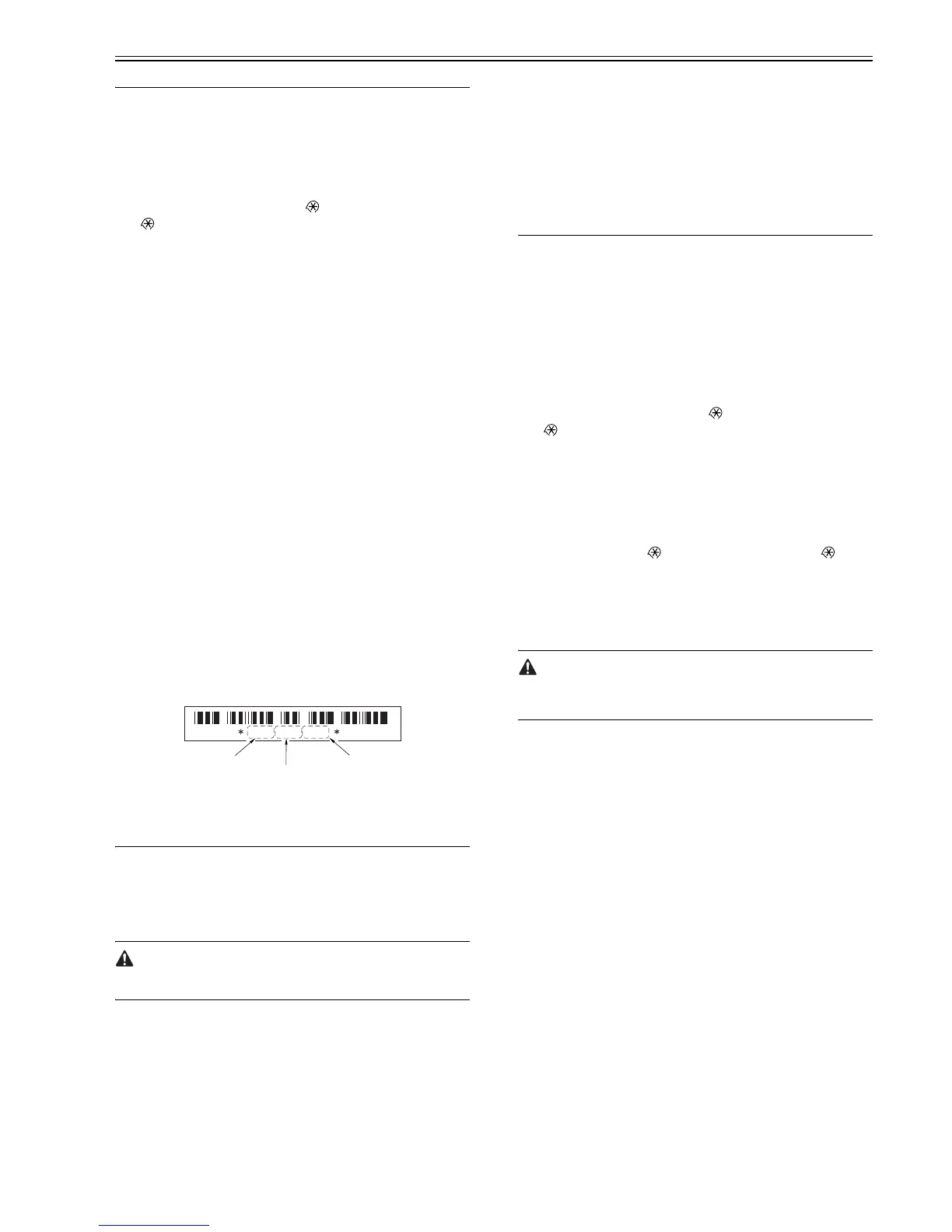
After replacing the copyboard glass, enter the correction values (X, Y, Z) of
the standard white plate which are indicated on the back of the new copy-
board glass in the service mode.
Correction value (X): Service mode>#SCAN>#SCAN NUMERIC>No.213
Correction value (Y): Service mode>#SCAN>#SCAN NUMERIC>No.214
Correction value (Z): Service mode>#SCAN>#SCAN NUMERIC>No.215
Also, rewrite the values on the service label.
F-11-1
11.2 Image Formation System
11.2.1 Procedure after Replacing the Developing
Assembly
0011-2545
iR2016J / iR2016 / iR2020 / / iR2016i / iR2020i
<Going through the Developer Idling Mode>
After replacing the developing assembly, go through the following steps
in the developing assembly idle rotation mode before installing the toner car-
tridge.
1) Plug the power cord into the outlet.
2) Open the front cover.
3) With the front cover open, turn on the main power switch.
4) When a message appears on the operation panel display, press the
following keys to enter the service mode:
Additional Functions key > 2 key > 8 key > Additional Functions key
5) Select "#PRINT" using the + or - key, and then press the OK key.
6) Select "#PRINT SW" using the + or - key, and hen press the OK key.
Confirm that the following message is displayed:
Message: #PRINT SW 001 00000000
7) Press the following keys and confirm the message:
# key > 1 key > 1 key
Message: #PRINT SW 011 00000000
8) Position the cursor to Bit-1 (second from right) using the + or - key, and
press the 1 key, and then confirm the following message:
Message: #PRINT SW 011 00000010
9) Press the OK key. Confirm that "SW 011" changes to "SW 012".
Message: #PRINT SW 012 00000000
10) Press the Reset key to exit the service mode.
11) Close the front cover. The machine will run in the developer idling mode
for about 1 minute.
12) When the machine stops, the idling mode ends.
Install, the toner cartridge following the above-mentioned procedure.
11.3 Electrical Components
11.3.1 Procedure after Replacing the Image Processor
PCB (iR2020/iR2020J/iR2016/iR2016J)
0011-2555
iR2016J / iR2016 / iR2020 /
If you have replaced the image processor PCB with a new one, perform the
following operations:
- Using the service support tool, download the latest firmware (System/
Boot).
- Input the all value printed on the service label affixed to the rear cover.
Make the following adjustments:
- Correction of output between CIS channels
1) Enter the service mode.
Sequentially press the User Mode key " ", 2 key, 8 key, and User Mode
key " " on the operation panel.
2) Using the arrow keys on the operation panel, display "TEST MODE".
3) Press the OK key.
4) Press the 2 key. "SCAN TEST" appears.
5) Press the 1 key.
After completion of the above steps, contact sensor output correction will be
performed and parameters will be set automatically.
- Read position adjustment (Stream reading: Only when the ADF is installed)
1) Enter the service mode.
Press the User Mode key " ", 2 key, 8 key, User Mode key " " on the
operation panel of the host machine.
2) Using the arrow keys on the operation panel, display "TEST MODE".
3) Press the OK key.
4) Press the 2 key. "SCAN TEST" appears.
5) Press the 3 key. "SHEET POS ADJ" appears.
The optical system starts scanning. Several seconds later, automatic adjust-
ment of the reading position finishes and "OK" appears.
If automatic adjustment fails, "NG" appears. Perform the following pro-
cedure:
Clean the white roller of the DADF and the document glass of the host ma-
chine, and then retry auto adjustment.
11.3.2 Procedure after Replacing the Image Processor
PCB (iR2020i/iR2016i)
0012-6051
iR2016i / iR2020i
If you have replaced the image processor PCB with a new one, perform the
following operations:
- Using the service support tool, download the latest firmware (System/Boot)
and language files.
- Delete the languages not used at the destination (Service mode > CLEAR
> FILE SYSTEM).
- Input the all value printed on the service label affixed to the rear cover.
Make the following adjustments:
- Correction of output between CIS channels
1) Enter the service mode.
Sequentially press the Additional functions key, 2 key, 8 key, and Additional
functions key on the operation panel.
2) Press the arrow key on the touch panel to display "TEST MODE".
3) Press [OK].
4) Press the [2] key to display "SCAN TEST".
5) Press the [1] key to display "SHADING".
6) Press [OK].
After completion of the above procedure, the contact sensor output is com-
pensated and parameters are set automatically.
After completion of automatic adjustment, "OK" is displayed.
- Read position adjustment (Stream reading: Only when the ADF is installed)
1) Enter the service mode.
Sequentially press the Additional functions key, 2 key, 8 key, and Additional
functions key on the operation panel.
2) Press the arrow key on the touch panel to display "TEST MODE".
3) Press [OK].
4) Press the [2] key to display "SCAN TEST".
5) Press the [3] key to display "SHEET POS ADJ".
6) Press [OK].
The optical system starts scanning. Several seconds later, automatic adjust-
820686679349
correcton
value (X)
correcton
value (Y)
correcton
value (Z)
 Loading...