COPYRIGHT
©
2001 CANON INC. 2000 2000 2000 2000 CANON iR2200/iR2800/iR3300 REV.0 MAR. 2001
CHAPTER 4 IMAGE FORMATION SYSTEM
4-18 P
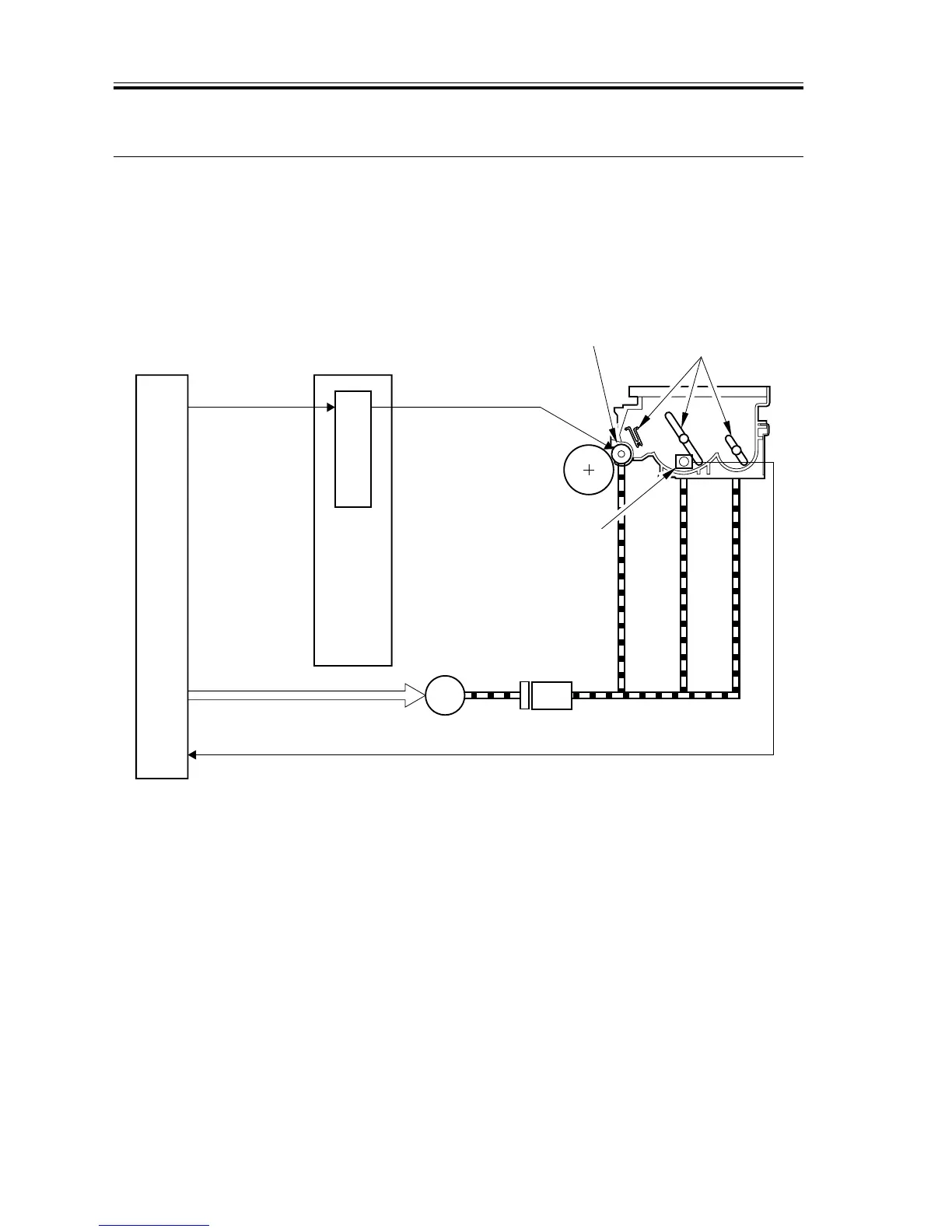
7 Developing Assembly
7.1 Outline
The developing assembly consists of the developing cylinder, toner sensor (S1), and toner
stirring rod; its is locked manually together with the developing rail using the locking lever.
The developing cylinder and the toner stirring rod are rotated by the drive of the main mo-
tor (M1) transmitted by way of the developing clutch (CL3).
F04-701-01
J130-1
DC controller PCB
Developing bias
control signal
Developing bias
Composite power
supply PCB
Main motor drive signal
J308
Toner detention signal
J302-5
J301 J136
Photosensitive
drum
Developing cylinder
Main
motor
Toner stirring rods
PW-CPU
M1
CL3
Developing
clutch
Toner sensor(S1)
 Loading...