,r.- ‘>
E. Main Motor Control Circuit
I
1. Outline
~
~
1
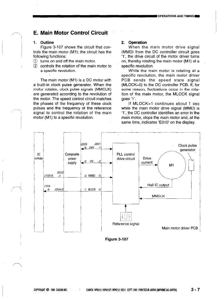
Figure 3-107 shows the circuit that con-
trols the main motor (Ml); the circuit has the
following functions:
0 turns on and off the main motor.
@ controls the rotation of the main motor to
a specific revolution.
The main motor (Ml) is a DC motor with
a built-in clock pulse generator. When the
motor rotates, clock pulse signals (MMCLK)
are generated according to the revolution of
the motor. The speed control circuit matches
the phases of the frequency of these clock
pulses and the frequency of the reference
signal to control the rotation of the main
I
motor (Ml) to a specific revolution.
2. ODeration
W’hen the main motor drive signal
(MMD) from the DC controller circuit goes
‘l’, the drive circuit of the motor driver turns
on, thereby rotating the main motor (Ml) at a
specific revolution.
While the main motor is rotating at a
specific revolution, the main motor driver
PCB sends the speed state signal
(MLOCK=O) to the DC controller PCB. If, for
some reason, fluctuations occur in the rota-
tion of the main motor, the MLOCK signal
goes ‘I’.
If MLOCK=l continues about 1 set
while the main motor drive signal (MMD) is
‘l’, the DC controller identifies an error in the
main motor, stops the main motor and, at the
same time, indicates ‘EOIO’ on the display.
,,- -.\I
\
DC
1lrOllE
J20
103-6 -7
104
-6 J204-
r
ic
I
I
31
+
(
$
I
I
I
I
I
,_
:omposite
power
SUPPlY
1
iJ:
+
I
1
I
7
I
i
I
I
I
I
I
I
j
!05
J90'
,-6 24V -'
-2 ov
-:
-2 MMD -!
-1 MLOCK -t
1
PLL control
drive circuit
I
57
int
Clock pulse
MMCLK
I
Reference signal
Main motor driver PCE
Figure 3-107
COPYRIGNT 6 1895 CANONINC.
CANON NP6012 ~NP6012FINP6212 REY.1 SEPT. 1895 PRINTED IN JAPAN (IMP& AU JAPONJ
3-7
 Loading...