F. Controlling the Developing/
Separation Static
Eliminator Bias
1. Outline
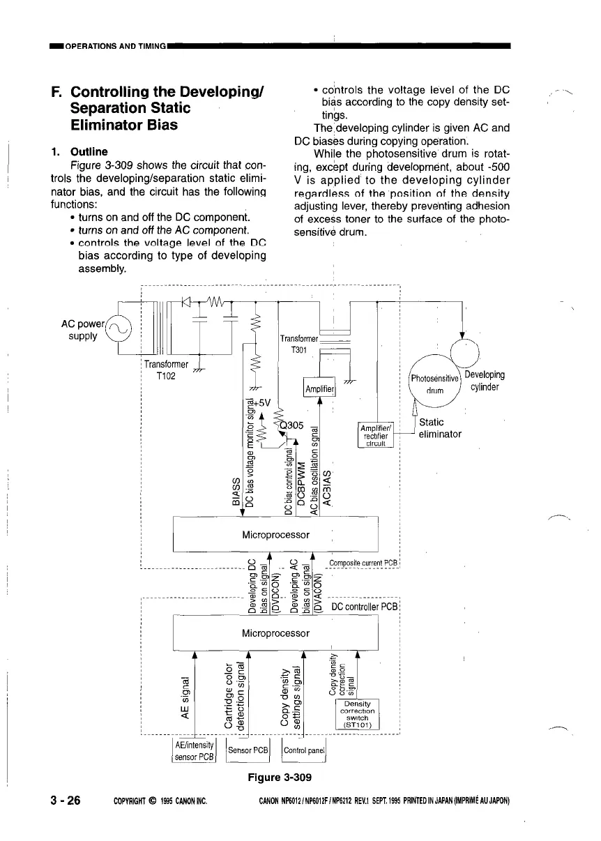
Figure 3-309 shows the circuit that con-
trols the developing/separation static elimi-
nator bias, and the circuit has the following
functions:
l turns on and off the DC component.
l turns on and off the AC component.
l controls the voltage level of the DC
bias according to type of developing
assembly.
AC power
SUPPlY
l co’ntrols the voltage level of the DC
bias according to the copy density set-
tings.
The:developing cylinder is given AC and
DC biases during copying operation.
While the photosensitive drum is rotat-
ing, except during development, about -500
V is applied to the developing cylinder
regardless of the position of the density
adjusting lever, thereby preventing adhesion
of excess toner to the surface of the photo-
sensitive drum.
ransformer
T102
L
Transformer_
Microprocessor
Microprocessor
Figure 3-309
Static
eliminator
3 - 26
COPYRIGHT 0 1995 CANONINC.
CANON NP6012/NP6012FINP6212 REV.1 SEPT.1995 PRlNTEDINJAPAN(IMPRIM~AUJAPON)
 Loading...