3. Controlling the Multifeeder Pick-Up
I
Roller
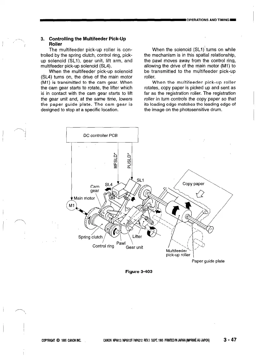
The multifeeder pick-up roller is con-
trolled by the spring clutch, control ring, pick-
up solenoid (SLl), gear unit, lift arm, and
multifeeder pick-up solenoid (SL4).
When the multifeeder pick-up solenoid
(SL4) turns on, the drive of the main motor
(Ml) is transmitted to the cam gear. When
the cam gear starts to rotate, the lifter which
isl in contact with the cam gear starts to lift
tiie gear unit and, at the same tirrie, lowers
the paper guide plate. The cam gear is
designed to stop at a specific location.
When the solenoid (SLl)’ turns on while
the mechanism is in this spatial relationship,
the pawl moves away from the control ring,
allowing the drive of the main motor (Ml) to
be transmitted to the multifeeder pick-up
roller.
When the multifeeder pick-up roller
rotates, copy paper is picked up and sent as
far as the registration roller. The registration
roller in turn controls the copy ‘paper so that
its leading edge matches the leading edge of
the image on the photosensitive drum.
_- ._
-\
I
1
DC controller PCB
I
Paper guide plate
Figure 3-403
COPYRIGHT 0 1995 CANONINC.
CANON NP60121NP6012FINP6212 REV.1 SEPT.1995 PRlNTEOINJAPAN(IMPRIM~AUJAPON)
3 - 47
 Loading...