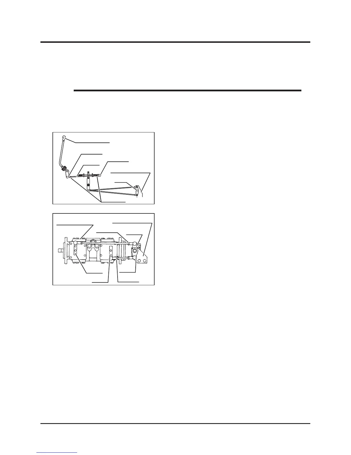
Steering Lever
1. Turn rod A and adjust so that the link portion
of steering lever is perpendicular.
(1) Loosen locknut.
(2) Turin rod A to adjust.
(3) After adjusting, tighten locknut securely.
2. Adjust with the bearing so that hydraulic
pump arm !, arm B, Intermediate Link, arm
C, and Arm D are perpendicular.
(1) Loosen locknut.
(2) Turn rods B and C to adjust.
(3) After adjusting, tighten locknut securely.
3. In the condition in Step 2, operate steering
lever fully to the front and rear, and check
that arms A and B both move the same angle
to the front and rear. If their angls differ, turn
rods B or C to adjust.
4. After carrying out of the adjustments in Steps
1 to 3, set steering lever to [N] position, push
parking brake switch to [(P) (parking)], and
start engine.
Operate parking brake switch to [Travel]
position, and if machine does not move, the
setting of [N] position is correct. If machine
moves, turn rods B and C again to carry out
fine adjustment of arms A and B and set
securely to the neutral position.
5. After completing the setting of neutral
position in Step 4, operate steering levers
fully to the front and rear and check that
machine travels to the straight line.
6. Coar the sliding surfaces on arms A and B
with grease.