45
ENG
ir33 universale +030220801 - rel. 2.1 - 21.06.2011
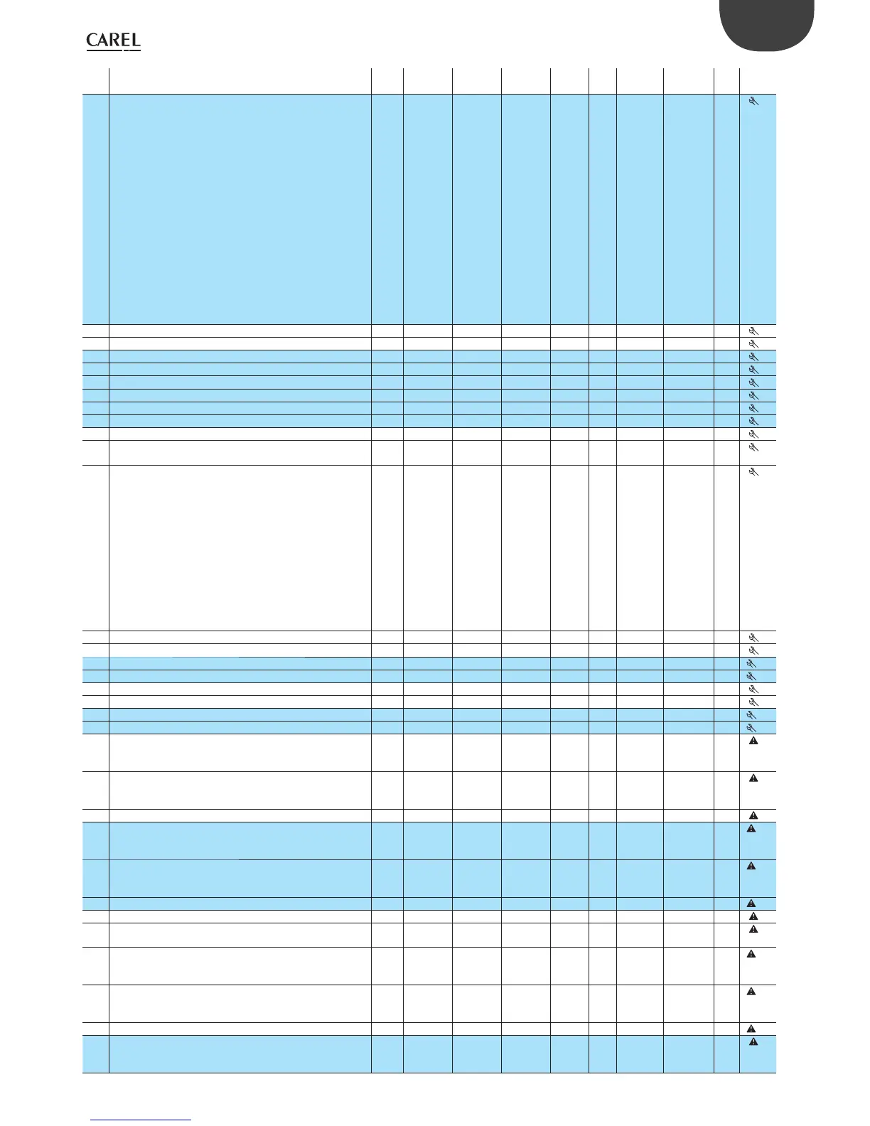
Par. Description Note Def Min Max UoM Type CAREL
SPV
ModBus® R/W Icon
c13 Probe type
0= Standard NTC range (-50T+110°C)
1= NTC-HT enhanced range (-10T+150°C)
2= Standard PTC range (-50T+150°C)
3= Standard PT1000 range (-50T+200°C)
4= PT1000 enhanced range (-199T+800°C)
5= Pt100 standard range (-50T+200°C)
6= Pt100 enhanced range (-199T+800°C)
7= Standard J thermocouple range (-50T+200°C)
8= Enhanced J thermocouple range (-100T+800°C)
9= Standard K thermocouple range (-50T+200°C)
10= Enhanced K thermocouple range (-100T+800°C)
11= 0 to 1 Vdc input
12=- 0.5 to 1.3 Vdc input
13= 0 to 10 Vdc input
14= 0 to 5 Vdc ratiometric
15= 0 to 20 mA input
16= 4 to 20 mA input
00
16 - I
20 120 R/W
P14 Probe 1 calibration 0 (0) -20 (-36) 20 (36) °C (°F) A 11 11 R/W
P15 Probe 2 calibration 0 (0) -20 (-36) 20 (36) °C (°F) A 12 12 R/W
P14 Probe 1 calibration 0 (0) -99 (-179) 99,9 (179) °C (°F) A 11 11 R/W
P15 Probe 2 calibration 0 (0) -99 (-179) 99,9 (179) °C (°F) A 12 12 R/W
c15 Minimum value for probe 1 with current/voltage signal 0 -199 c16 - A 13 13 R/W
c16 Maximum value for probe 1 with current/voltage signal 100 c15 800 - A 14 14 R/W
d15 Minimum value for probe 2 with current/voltage signal 0 -199 d16 - A 29 29 R/W
d16 Maximum value for probe 2 with current/voltage signal 100 d15 800 - A 30 30 R/W
c17 Probe disturbance lter 4 1 15 - I 21 121 R/W
c18 Temperature unit of measure
0=°C, 1=°F
0 0 1 - D 26 26 R/W
c19 Function of probe 2
0= not enabled
1= di erential operation
2= compensation in cooling
3= compensation in heating
4= compensation always active
5= enable logic on absolute set point
6= enable logic on di erential set point
7= independent operation (circuit 1+circuit 2)
8= control on higher probe value
9= control on lower probe value
10= control set point set by B2
11= automatic heating/cooling changeover from B2
0 0 11 - I 22 122 R/W
c21 Minimum value of set point 1 -50 (-58) -50 (-58) c22 °C (°F) A 15 15 R/W
c22 Maximum value of set point 1 60 (140) c21 150 (302) °C (°F) A 16 16 R/W
c21 Minimum value of set point 1 -50 (-58) -199 (-199) c22 °C (°F) A 15 15 R/W
c22 Maximum value of set point 1 110 (230) c21 800 (800) °C (°F) A 16 16 R/W
c23 Minimum value of set point 2 -50 (-58) -50 (-58) c24 °C (°F) A 17 17 R/W
c24 Maximum value of set point 2 60 (140) c23 150 (302) °C (°F) A 18 18 R/W
c23 Minimum value of set point 2 -50 (-58) -199 (-199) c24 °C (°F) A 17 17 R/W
c24 Maximum value of set point 2 110 (230) c23 800 (800) °C (°F) A 18 18 R/W
P25 Low temperature alarm threshold on probe 1
if P29=0, P25=0: threshold disabled
if P29=1, P25=-50: threshold disabled
-50 (-58) -50 (-58) P26 °C (°F) A 19 19 R/W
P26 High temperature alarm threshold on probe 1
if P29=0, P26=0: threshold disabled
if P29=1, P26=150: threshold disabled
150 (302) P25 150 (302) °C (°F) A 20 20 R/W
P27 Alarm di erential on probe 1 2 (3,6) 0 (0) 50 (90) °C (°F) A 21 21 R/W
P25 Low temperature alarm threshold on probe 1
if P29=0, P25=0: threshold disabled
if P29=1, P25=-199: threshold disabled
-50 (-58) -199 (-199) P26 °C (°F) A 19 19 R/W
P26 High temperature alarm threshold on probe 1
if P29=0, P26=0: threshold disabled
if P29=1, P26=800: threshold disabled
150 (302) P25 800 (800) °C (°F) A 20 20 R/W
P27 Alarm di erential on probe 1 2 (3,6) 0 (0) 99,9 (179) °C (°F) A 21 21 R/W
P28 Alarm delay time on probe 1(**) 120 0 250 min (s) I 23 123 R/W
P29 Type of alarm threshold on probe 1
0=relative; 1=absolute
1 0 1 - D 27 27 R/W
P30 Low temperature alarm threshold on probe 2
if P34=0, P30=0: threshold disabled
if P34=1, P30=-50: threshold disabled
-50 (-58) -50 (-58) P31 °C (°F) A 31 31 R/W
P31 High temperature alarm threshold on probe 2
if P34=0, P31=0: threshold disabled
if P34=1, P31=150: threshold disabled
150 (302) P30 150 (302) °C (°F) A 32 32 R/W
P32 Alarm di erential on probe 2 2 (3,6) 0 (0) 50 (90) °C (°F) A 33 33 R/W
P30 Low temperature alarm threshold on probe 2
if P34=0, P30=0: threshold disabled
if P34=1, P30=-199: threshold disabled
-50 (-58) -199 (-199) P31 °C (°F) A 31 31 R/W
 Loading...


