46
ENG
ir33 universale +030220801 - rel. 2.1 - 21.06.2011
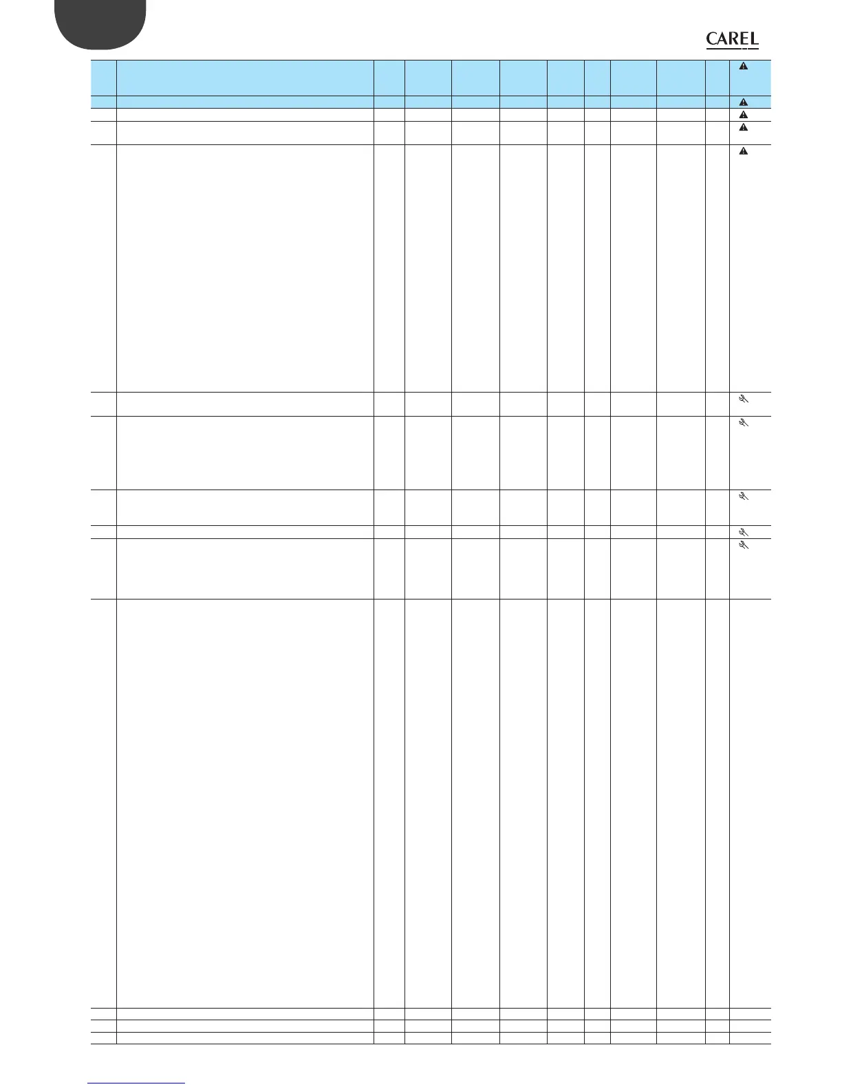
P31 High temperature alarm threshold on probe 2
if P34=0, P31=0: threshold disabled
if P34=1, P31=800: threshold disabled
150 (302) P30 800 (800) °C (°F) A 32 32 R/W
P32 Alarm di erential on probe 2 2 (3,6) 0(0) 99,9 (179) °C (°F) A 33 33 R/W
P33 Alarm delay time on probe 2(**) 120 0 250 min (s) I 113 213 R/W
P34 Type of alarm threshold on probe 2
0=relative; 1=absolute
1 0 1 - D 37 37 R/W
c29 Digital input 1
0= Input not active
1= Immediate external alarm, Automatic reset (circuit 1)
2= Immediate external alarm, Manual reset (circuit 1)
3= Delayed external alarm (P28), Manual reset (circuit 1)
4= ON/OFF control in relation to status of digital input
5= Activation/deactivation working cycle from button
6= Override outputs (circuit 1)
7= Signal only alarm E17, delayed (P33)
8= Signal only alarm E17, immediate
9= Immediate external alarm, Automatic reset (circuit 2)
10= Immediate external alarm, Manual reset (circuit 2)
11= Delayed external alarm (P33), Manual reset (circuit 2)
12= Override outputs (circuit 2)
13 = Immediate external alarm with automatic reset (circuit 1)
14 = Immediate external alarm with manual reset (circuit 1)
15 = Delayed external alarm (P28) with manual reset (circuit 1)
Validity: c0 other than 6,7, and if c33= 1
with “dependence”=16 and 17. In the event of alarms, the
status of the relay depends on c31 or d31
0 0 12 - I 24 124 R/W
c30 Digital input 2
See c29
0 0 12 - I 25 125 R/W
c31 Status of control outputs in circuit 1 in the event of an alarm
from digital input
0= All outputs OFF
1= All outputs ON
2= ”Reverse” outputs OFF, others unchanged
3= “Direct” outputs OFF, others unchanged
0 0 3 - I 26 126 R/W
d31 Status of control outputs in circuit 2 in the event of an alarm
from digital input
See c31
0 0 3 - I 114 214 R/W
c32 Serial connection address 1 0 207 - I 27 127 R/W
c33 Special operation
0=Disabled
1= Enabled
(Before modifying make sure the required start mode has
been selected and programmed (c0))
0 0 1 - D 28 28 R/W
c34 Output 1 dependence
0= Output not enabled
1= Control output (St1,P1)
2= Control output (St2,P2)
3= Generic alarm, circuit 1 (relay OFF)
4= Generic alarm, circuit 1 (relay ON)
5= Serious alarm, circuit 1 and E04 (relay OFF)
6= Serious alarm, circuit 1 and E04 (relay ON)
7= Serious alarm, circuit 1 and E05 (relay OFF)
8= Serious alarm, circuit 1 and E05 (relay ON)
9= Alarm E05 (relay OFF)
10= Alarm E05 (relay ON)
11= Alarm E04 (relay OFF)
12= Alarm E04 (relay ON)
13= Serious alarm, circuit 1+2 (relay OFF)
14= Serious alarm, circuit 1+2 (relay ON)
15= Timer
16= Control output with change set point and reverse opera-
ting logic from digital input 1
17= Control output with change set point and maintain
operating logic from digital input 1
18= ON/OFF status signal
19= Generic alarm, circuit 2 (relay OFF)
20= Generic alarm, circuit 2 (relay ON)
21= Serious alarm, circuit 2 and E15 (relay OFF)
22= Serious alarm, circuit 2 and E15 (relay ON)
23= Serious alarm, circuit 2 and E16 (relay OFF)
24= Serious alarm, circuit 2 and E16 (relay ON)
25= Alarm E16 (relay OFF)
26= Alarm E16 (relay ON)
27= Alarm E15 (relay OFF)
28= Alarm E15 (relay ON)
29= Alarm E17 (relay OFF)
1 0 29 - I 28 128 R/W 1
c35 Type of output 1 0 (
) 0 1 - D 29 29 R/W 1
c36 Output 1 activation -25 (
) -100 100 % I 29 129 R/W 1
c37 Output 1 di erential/logic 25 (
) -100 100 % I 30 130 R/W 1
 Loading...


