EasyManua.ls Logo

Carestream CS 8100 - User Manual

Carestream CS 8100
56 pages
Print Icon
To Next Page IconTo Next Page
Loading...
User Guide
CS 8100 & CS 8100 3D Family
CS 8100, CS 8100 Access, CS 8100SC, CS 8100SC Access, CS 8100SC 3D
& CS 8100SC 3D Access

Table of Contents

Question and Answer IconNeed help?

Do you have a question about the Carestream CS 8100 and is the answer not in the manual?

Summary

Conventions in This Guide

Guide Message Conventions

Explains special messages used in the guide for warnings and notes.

Cephalometric Modality Overview

CS 8100 Family Product Line

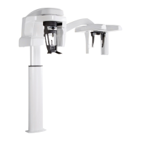
Lists the different models within the CS 8100 Family.

CS 8100 3 D Family Product Line

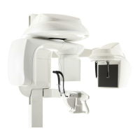
Lists the different models within the CS 8100 3D Family.

Mobile Components

CS 8100 SC Mobile Components Diagram

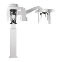
Image showing mobile components of CS 8100SC.

CS 8100 SC 3 D Mobile Components Diagram

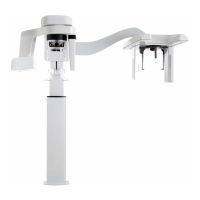
Image showing mobile components of CS 8100SC 3D.

General Functional Components

CS 8100 SC Component Identification

Diagram labeling functional components of the CS 8100SC unit.

Key Component Labels (1-10)

Identifies key operational components like arms, headrests, sensors.

Key Component Labels (11-19)

Identifies structural and software components like column, indicators, computer.

CS 8100 3 D Functional Components

CS 8100 3 D Component Identification

Diagram labeling functional components of the CS 8100 3D unit.

Key Component Labels (1-10)

Identifies key operational components for CS 8100 3D.

Key Component Labels (11-19)

Identifies structural and software components for CS 8100 3D.

Digital Sensor Locations

CS 8100 SC Sensor Location Diagram

Image showing sensor locations for CS 8100SC.

CS 8100 SC 3 D Sensor Location Diagram

Image showing sensor locations for CS 8100SC 3D.

Head and Chin Rest (CS 8100 Family)

CS 8100 Family Head;Chin Rest Diagram

Diagram labeling functional components of the CS 8100 Family head/chin rest.

Head;Chin Rest Component Labels (1-4)

Identifies positioning panel, knobs, rests, and indicators.

Head;Chin Rest Component Labels (5-8)

Identifies bite block support, chin rest, grips, and indicators.

Head and Chin Rest (CS 8100 3 D)

CS 8100 3 D Head;Chin Rest Diagram

Diagram labeling functional components of the CS 8100 3D Family head/chin rest.

Head;Chin Rest Component Labels (1-3)

Identifies positioning panel, temple supports, and adjustment knob.

Head;Chin Rest Component Labels (4-6)

Identifies bite block support, chin rest, and hand grips.

Positioning Panel Controls

Positioning Panel Functionality Overview

Describes the function of the positioning panel.

CS 8100 Family Positioning Panel Diagram

Diagram of the positioning panel for the CS 8100 Family.

CS 8100 3 D Family Positioning Panel Diagram

Diagram of the positioning panel for the CS 8100 3D Family.

Key Positioning Panel Controls

Identifies Height Adjustment buttons, Ready Indicator LED, and adjustment knobs.

Cephalometric Positioning Accessories

Accessory Descriptions

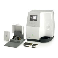
Lists accessories for patient positioning.

Positioning Accessories Table

Table detailing positioning accessories and their descriptions.

Ear Cone Sheaths and Carpus Panel

Describes ear cone sheaths and identifies the optional carpus panel.

Frankfort Positioning Indicator

Identifies the Frankfort positioning indicator.

X-ray Remote Control Operation

Remote Control Functionality Explained

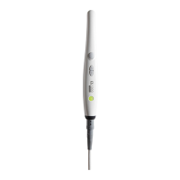
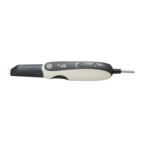
Explains the function of the X-ray remote control.

X-ray Remote Control Diagram

Diagram of the X-ray remote control.

Exposure Button Function

Identifies the button to launch image acquisition.

Imaging Software Overview

Computer System Requirements for Software

Details minimum computer system requirements for the software.

Software Components Overview

Lists the software components used by the modality.

CS Imaging Software Description

Describes the CS Imaging Software interface.

Acquisition Interface Features

Describes the acquisition interface features.

Cephalometric Acquisition Interface Details

Acquisition Interface Functionality Explained

Explains the purpose of the acquisition interface.

Acquisition Interface Diagram and Labels

Diagram of the cephalometric acquisition interface.

Interface Information and Status Displays

Identifies information, preview, parameter, and status displays.

Interface Controls and Indicators Summary

Identifies buttons, LEDs, and indicators for interface operation.

Acquisition Interface Program Pane

Program Pane Functionality Explained

Explains the function of the Program Pane.

Program Pane Interface Diagram

Diagram of the Program Pane.

Radiological Exam Options Listing

Lists available radiological exam types.

Field of View (FoV) Options Listing

Lists available Field of View (FoV) options.

Acquisition Interface Patient Pane

Patient Pane Functionality Explained

Explains the function of the Patient Pane.

Patient Pane Interface Diagram

Diagram of the Patient Pane.

Patient Type Parameter Configuration

Details patient type parameters for image acquisition.

Pediatric and Adult Patient Modes

Describes pediatric and adult patient mode settings.

Acquisition Interface Parameter Pane

Parameter Pane Functionality Explained

Explains the function of the Parameter Pane.

Parameter Pane Interface Diagram

Diagram of the Parameter Pane.

Exposure Setting Options Explained

Identifies exposure setting options (kV, mA).

Parameter Fine-Tuning Controls Explained

Identifies buttons for fine-tuning exposure parameters.

Getting Started with the Unit

Unit Power-On Procedure

Provides steps for powering on the unit.

X-ray Tube Life Extension Procedures

Describes procedures to increase X-ray tube lifespan.

Firewall and Network Configuration

Steps for Firewall;Network Settings

Outlines steps to configure firewall/network settings.

Accessing the Cephalometric Interface

Steps to Launch Acquisition Interface

Provides steps to launch the acquisition interface.

Acquiring a Lateral Cephalometric Image

Prerequisites for Lateral Image Acquisition

Prerequisites for image acquisition.

Preparing Unit for Lateral Image Acquisition

Details preparing the unit and setting parameters for acquisition.

Patient Preparation and Positioning for Lateral Image

Patient Preparation Steps for Lateral Image

Steps for patient preparation and positioning.

Remove Metal Objects and Wear Lead Apron

Instruction to remove metal objects and wear a lead apron.

Positioning Head Clamps and Ear Cones

Instruction to extend head clamp bars and position ear cones.

Patient Positioning Instructions for Lateral Image

Instructions for patient positioning.

Launching the X-ray and Dose Information

X-ray Launch Procedure and Remote Control Use

Steps to initiate X-ray acquisition using remote control.

Post-Acquisition Steps and Image Check

Steps after image acquisition and quality check.

X-ray Dose Emission Information Overview

Information on radiation compliance and dose viewing.

Radiation Directive Compliance EURATOM 97;43

States compliance with radiation directive.

Acquiring Frontal AP and PA Images

Prerequisites for Frontal AP;PA Acquisition

Prerequisites for image acquisition.

Setting Up for Frontal AP Exam

Instruction to position head clamps for frontal AP exam.

Selecting PA Exam and FoV Options

Instruction to select PA exam and Field of View options.

Acquiring an Oblique Image

Prerequisites for Oblique Image Acquisition

Prerequisites for image acquisition.

Setting Up for Oblique Exam

Instruction to position head clamps for oblique exam.

Selecting FoV and Patient Pane for Oblique

Instruction to select FoV and access patient pane for oblique.

Patient Type Selection for Oblique Image

Lists available patient types.

Patient Preparation and Positioning for Oblique Image

Patient Preparation for Oblique Image

Steps for patient preparation and positioning.

Remove Metal Objects and Wear Lead Apron

Instruction to remove metal objects and wear a lead apron.

Positioning Head Clamps for Oblique Image

Instruction to extend head clamp bars.

Patient Positioning Instructions for Oblique Image

Instructions for patient positioning.

Launching the X-ray and Dose Information

Adjusting Ear Cones and Retracting Head Clamps

Instruction to adjust ear cones and retract head clamp bars.

Positioning Nasion Support for Oblique Image

Instruction to position the nasion support.

X-ray Launch Procedure for Oblique Image

Steps to initiate X-ray acquisition.

Acquiring a Submento-Vertex Image

Prerequisites for Submento-Vertex Acquisition

Prerequisites for image acquisition.

Setting Up for Submento-Vertex Exam

Instruction to position head clamps for frontal AP exam.

Selecting FoV and Patient Pane for Submento-Vertex

Instruction to select submento-vertex exam and access patient pane.

Accessing Patient Pane for Submento-Vertex

Instruction to access the patient pane.

Patient Preparation and Positioning for Submento-Vertex Image

Patient Type Selection for Submento-Vertex

Lists available patient types.

Adjusting Parameters for Submento-Vertex (Optional)

Optional step to adjust parameters.

Patient Preparation Steps for Submento-Vertex

Steps for patient preparation.

Patient Positioning Steps for Submento-Vertex

Instructions for patient positioning.

Launching the X-ray and Dose Information

X-ray Launch Procedure and Remote Control Use

Steps to initiate X-ray acquisition using remote control.

Post-Acquisition Steps and Image Check

Steps after image acquisition and quality check.

X-ray Dose Emission Information Overview

Information on radiation compliance and dose viewing.

Radiation Directive Compliance EURATOM 97;43

States compliance with radiation directive.

Acquiring a Carpus Image

Prerequisites for Carpus Image Acquisition

Prerequisites for image acquisition.

Setting Up for Carpus Exam

Instruction to position head clamps for frontal AP exam.

Connecting the Carpus Panel

Steps to connect the carpus panel.

Patient Preparation and Positioning for Carpus Image

Carpus FoV and Patient Pane Selection

Instruction to select FoV for carpus image.

Patient Type Selection for Carpus Image

Lists available patient types.

Adjusting Parameters for Carpus Image (Optional)

Optional step to adjust parameters.

Patient Preparation for Carpus Image

Steps for patient preparation and positioning.

Launching the X-ray and Dose Information

Wear Lead Apron with Thyroid Collar for Carpus

Instruction to wear a lead apron with thyroid collar for carpus.

Patient Positioning for Carpus Image Acquisition

Instructions for patient positioning for carpus.

X-ray Launch Procedure for Carpus Image

Steps to initiate X-ray acquisition.

Maintenance Procedures

Maintenance Activities Overview

Introduction to maintenance activities.

Monthly Maintenance Tasks

Describes monthly maintenance tasks.

Annual Maintenance Tasks

Describes annual maintenance tasks.

Image Quality Control Procedures

Details procedures for controlling image quality.

Image Quality Control Testing

Performing Image Quality Tests

Instruction to perform image quality tests.

Contact Information

Manufacturers Address and Details

Provides the manufacturer's contact address.

Factory Address Details

Provides the factory address.

Authorized Representatives Listing

Lists authorized representatives.

Carestream CS 8100 Specifications

General IconGeneral
User InterfaceTouchscreen
Focal Spot Size0.5 mm
X-Ray Generator Voltage60-90 kV
X-Ray Generator Current2-15 mA
TypeDigital Panoramic and Cephalometric System
TechnologyDigital Imaging
Sensor TypeCCD
SoftwareCarestream Imaging Software
Power Requirements50/60 Hz
Cephalometric Scan Time3-10 seconds

Related product manuals