2–1 T-361
SECTION 2
DESCRIPTION
2.1 INTRODUCTION
The Carrier Transicold model 69RG15 clip-on diesel driven generator sets provide electrical power for all-electric
refrigeration units.
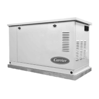
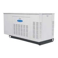
The generator set (see Figure 2.1 and Figure 2.2) consists of a diesel engine directly connected to an alternating
current generator and mounted in a structural steel frame. The engine is a vertical in-line, four cylinder diesel man-
ufactured by Kubota. The generator is a 15 kW, permanent, dual bearing type. Generator sets will start at 50Hz.
Once the unit is running, the voltage controller will read the voltage output of the generator and adjust accordingly
to keep the voltage within ISO limits. As the Container becomes loaded, voltage drops and current increases, caus-
ing the generator set to switch windings or speed based on power demand and ambient conditions. The unit will
typically run at 50Hz and will vary generator output via winding selection. The speed change to 60 Hz will typically
occur when the ambient temperature is high and the unit is heavily loaded.
Electrical controls are mounted in a control box with operating controls and gauges mounted on a control panel
(which also serves as the control box cover). The control panel components are protected by a deflector assembly.
Auxiliary engine equipment consists of the battery, solid state battery charging system, “spin-on” lube oil filter, fuel
filter and other necessary components for proper unit operation. The water pump and the radiator cooling fan are
belt-driven from the engine crankshaft. All references to engine are as viewed from the fly wheel end.
The 69RG15 is available as a standard configuration, with an Auto Restart option. The Auto Restart option auto-
matically restarts the unit in the event of specific unit shutdowns.
Carrier Transicold’s Ecodriven dual speed option provides an energy saving alternative to the practice of continu-
ously running the generator at full speed. This speed reduction results in increased fuel economy, reduced carbon
footprint, and lowers operating costs.
2.2 CONFIGURATION IDENTIFICATION
Generator set identification information is provided on a label located below the right mounting clamp (front facing).
The label provides the generator set model number, serial number and parts identification number (PID). The
model number identifies the overall configuration while the PID provides information on specific optional equipment
and differences in detailed parts.
The model number, serial number and PID number must be included when ordering parts and inquiring about your
unit.
Separately bound manuals covering the diesel engine are also available. (See Table 2–1).
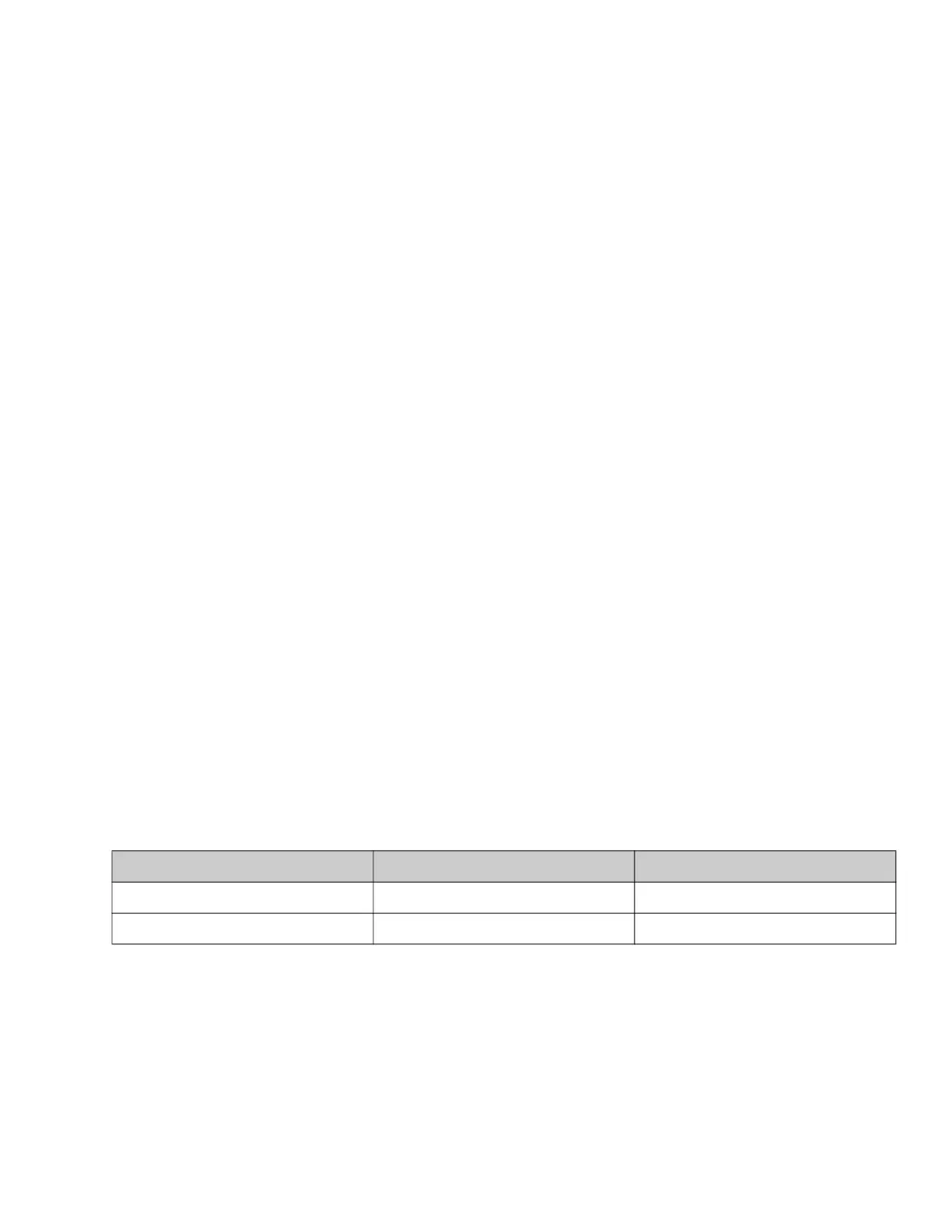
Table 2–1 Model Chart
Manual / Form Number Equipment Covered Type of Manual
62-11335 V2203-DI Engine Part List
62-11362 V2203-DI Workshop

 Loading...