30
DIAGNOSTICS
The control system has many fault tracing aid functions,
protecting the unit against risks that could result in the failure
of the unit.
operating conditions. If an operating fault is detected, the
alarm is triggered.
8.1 - Control diagnostics
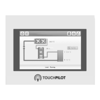
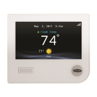
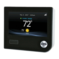
The user interface enables the quick display of the unit status:
The blinking bell icon indicates that there is an alarm,
but the unit is still running.
The highlighted bell icon indicates that the unit is shut
down due to a detected fault.
All information regarding the existing alarms (current and
past alarms) can be found in the Alarm menu.
Viewing alarm information
Alarm menu Date Hour Code Description
Current Alarms
(basic access)
• • •
Alarm Historic
(basic access)
• • •
Major Alarm
Historic
(basic access)
• • •
Reset Alarms
(user access)
•
8.2 -
IMPORTANT: E-mail notications can be congured only
by Carrier service technicians.
8.3 - Displaying current alarms
The Current alarms menu may display up to 10 current alarms.
To access the list of currently active alarms
1. Press the Alarm button in the upper-right part of the screen.
2. Select Current Alarms.
8.4 - Resetting alarms
The alarm can be reset either automatically by the control
or manually through the touch panel display or the web
interface (in the Reset Alarms menu).
• The Reset alarms menu displays up to 5 alarm codes
• Alarms can be reset without stopping the machine.
• Only logged-in users can reset the alarms on the unit.
To reset the alarm manually
1. Press the Alarm button in the upper-right part of the screen.
2. Select Reset Alarms.
3. Set “Alarm Reset” to Yes.
IMPORTANT: Not all alarms can be reset by the user. Some
alarms are reset automatically when operating conditions
return to normal.
CAUTION: In the event of a power supply interrupt, the
unit restarts automatically without the need for an external
command. However, any faults active when the supply is
interrupted are saved and may in certain cases prevent a
circuit or a unit from restarting.
8.5 - Alarm history
recent major alarms. Alarm history can be accessed through
To access the alarm history
1. Press the Alarm button in the upper-right part of the screen.
2. Select Alarm Historic or Major Alarm Historic.
3. The history of alarms will be displayed.
8.6 - Alarms description
The following table includes a list of alarms that might appear
on the unit.
No. Code Alarm description Reset type Action taken Possible cause
Thermistor failures
1 15001 Cooler Entering Fluid Thermistor Automatic, if thermistor
reading returns to normal
Unit shuts down Defective thermistor
2 15002 Cooler Leaving Fluid Thermistor As above Unit shuts down As above
3 15006 Condenser Entering Fluid Thermistor As above Unit shuts down As above
4 15007 Condenser Leaving Fluid Thermistor As above Unit shuts down As above
5 15011 Master/Slave Common Fluid Thermistor As above Master/slave operation is
disabled and the unit returns
to the stand-alone mode
As above
6 15012 Circuit A Suction Gas Thermistor As above Circuit A shuts down As above
7 15013 Circuit B Suction Gas Thermistor As above Circuit B shuts down As above
8 15014 Circuit C Suction Gas Thermistor Not applicable to this unit
9 15015 Circuit A Discharge Gas Thermistor Automatic, if thermistor
reading returns to normal
Circuit A shuts down Defective thermistor
10 15016 Circuit B Discharge Gas Thermistor As above Circuit B shuts down As above
11 15017 Circuit C Discharge Gas Thermistor Not applicable to this unit