6
3 - HARDWARE DESCRIPTION
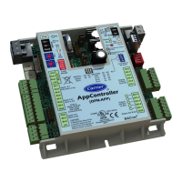
3.1 - Control boards
manage all inputs and outputs of the controller. TCPM board
is used to control and protect the operation of screw
detection option. At the same time, Energy Management
Module (EMM) requires an additional SIOB board to be
accordingly starts the program that controls the unit.
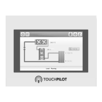
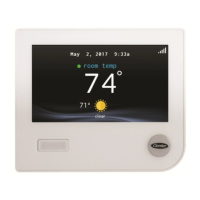
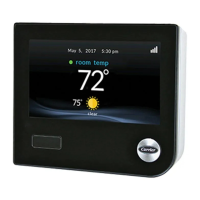
The unit is equipped with the Touch Pilot user interface
(5-inch colour LCD touch screen).
The electrical box includes all boards controlling the unit
and the user interface.
3.2 - Power supply to boards
All boards are supplied from a common 24 VAC supply
referred to earth.
CAUTION: Maintain correct polarity when connecting the
power supply to the boards, otherwise the boards may be
damaged.
automatically without the need for an external command.
the unit from restarting.
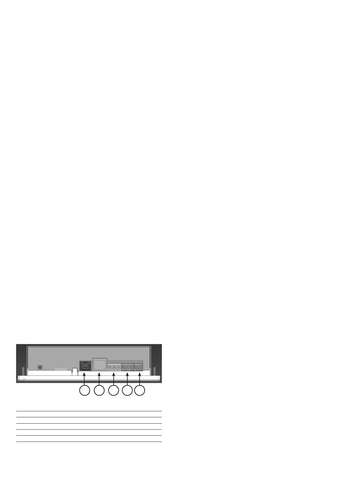
3.3 - Connections of the main controller
Connections are located on the bottom side of the main
controller.
port is used to connect to CCN (Carrier Comfort Network)
and the second RS485 port is used for internal communication
(LEN).
The Ethernet port allows for TCP/IP communication or BMS
(Building Management System) connection thanks to
BACnet/IP communication.
Connections of the main controller:
1 USB connector
2 Ethernet connector
3 CCN connector
4 LEN connector (RS485)
5 Power supply (24 VAC)
3.4 - Light emitting diodes on boards
All boards continuously check and indicate the proper
operation of their electronic circuits. A light emitting diode
(LED) lights on each board when it is operating properly.
•
SIOB board indicates correct operation. A different
rate indicates a board or a software failure.
•
indicates a LEN bus wiring problem.
3.5 - Pressure transducers
Two types of electronic sensors (high and low pressure) are
connected to the SIOB board.
Discharge pressure sensors (high pressure type)
These sensors measure the discharge pressure in each circuit.
They are used to control head pressure or high pressure load
shedding. Discharge pressure sensors are mounted on the
discharge line piping of each circuit.
Suction pressure sensors (low pressure type)
These sensors measure the suction pressure in each circuit.
They are used for control. Suction pressure sensors are located
on the suction piping of each circuit.
Oil pressure sensors (high pressure type)
These sensors measure the oil pressure of each compressor.
Oil pressure sensors are located at the oil port of the
compressor. The economizer pressure is subtracted from this
Economizer pressure sensors (high pressure type)
These sensors measure the intermediate pressure between
high and low pressure. They are used to control the economizer
performance.
3.6 - Temperature sensors
Temperature sensors constantly measure the temperature of
operation of the system.
Evaporator entering and leaving water temperature sensors
box. They are used for capacity control and safety purposes.
Condenser entering and leaving water temperature sensors
temperatures on the condenser side.
Suction gas temperature sensor
This sensor is used to control the suction gas temperature.
It is located at the suction line of each compressor.
Discharge gas temperature sensor
This sensor is used to control the discharge gas temperature,
and permits control of the discharge superheat temperature.
It is located at the discharge line of the compressor.
Oil temperature sensor
This sensor is used to control the oil temperature of each
compressor.
1 2 43
5