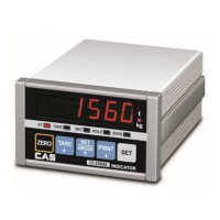
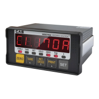
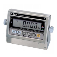
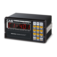
`
53
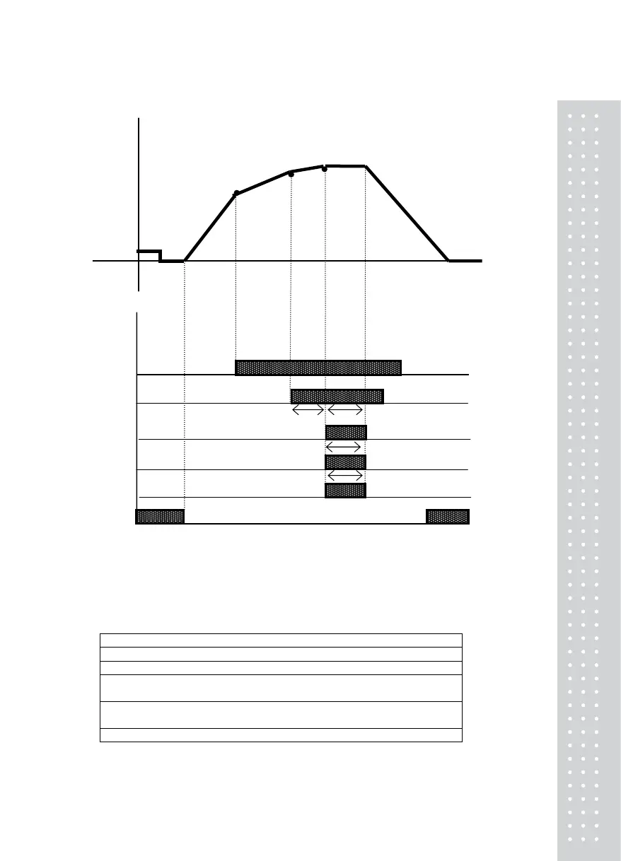
<Limit mode 2> Relay Operation Graph when #2 of F51 is set
Weight Stable
Step2 – Free Fall
Step1
Near Zero
SP1 Output 1
SP2 Output 2
SP3 Output 3
SP4 Output 4
Finish Output 5
Near Zero Output 6
Note.
1. Set value input requirement: Step2– Free Fall > Step1
2. Near zero output is according to the specified range in F57.
3. T1: Refer to F52 (Delay time of weighing Finish relay output)
T2: Refer to F53 (Operation time of weighing Finish relay output)
T5: Refer to F56 (Operation(ON) time of Weighing NG relay output)
4. Relay Output
SP1: ON when the set value of Step1 is reached
SP2: ON when the set value of Step1 – free fall is reached
Finish : On after T1 (set time), ON after T2 (set time)
Lowest Limit NG: Upon weighing finish, ON when lower than the set value of Step2 –
Lowest Limit NG
Upper Limit NG: Upon weighing finish, ON when higher than the set value of Step2 +
Upper Limit NG
Near zero: F57 set value ≥ 0 range output
5. SP1,2 ‘s status lamps in the front panel are operated in the same manner as the RELAY output.
T1
T2
T5
T5
 Loading...