`
5
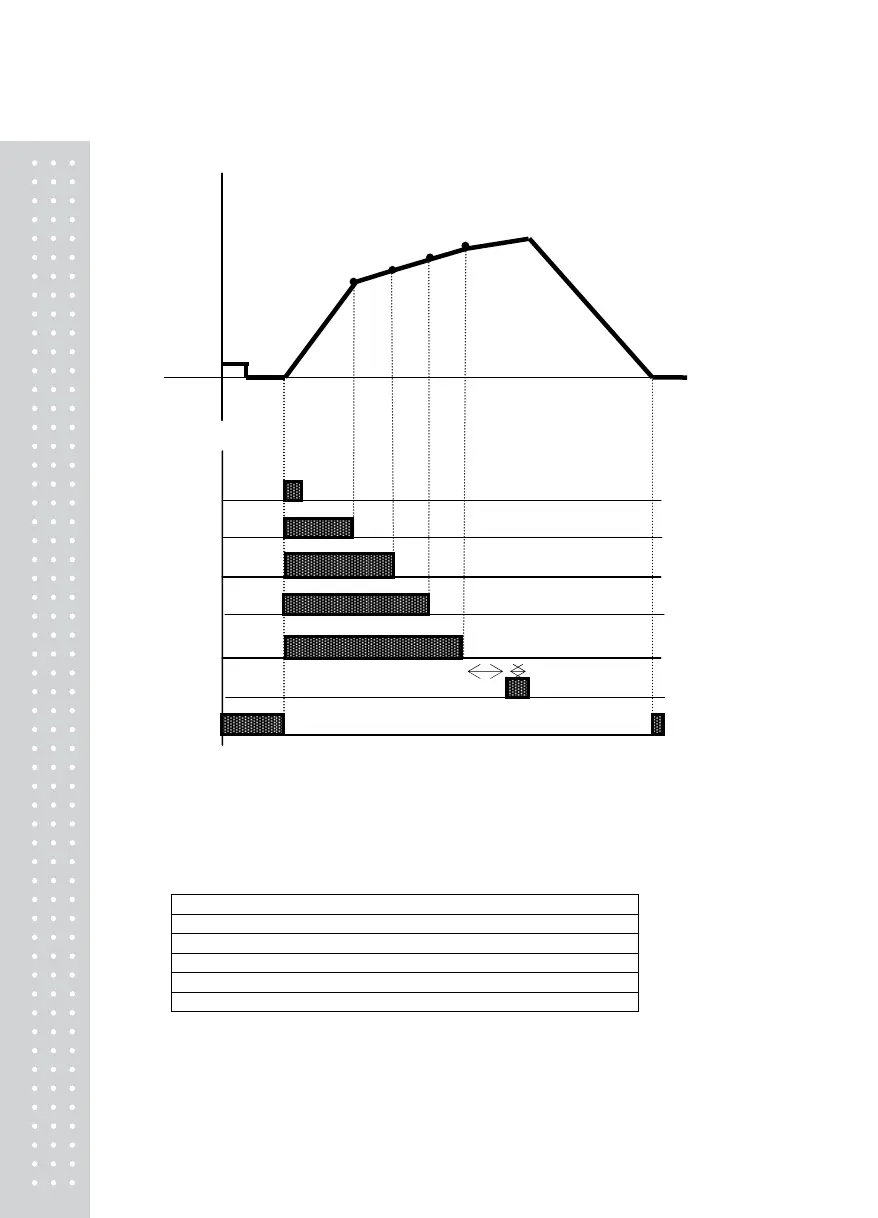
<Packer Mode 1> Relay Operation Graph when #3 of F51 is Set
Weight
Step4
Step3
Step2
Step1
Near Zero
Start External Input
SP1 Output 1
SP2 Output2
SP3 Output 3
SP4 Output 4
Finish Output 5
Near Zero Output 6
Note.
1. Required set value input: Step4> Step3 > Step2> Step1
2. Near zero output is according to the specified range in F57.
3. T1: Refer to F52 (Delay time of weighing Finish relay output)
T2: Refer to F53 (Operation time of weighing Finish relay output)
4. Relay Output
SP1: ON when the set value of Step1 is reached
SP2: ON when the set value of Step2 is reached
SP3: ON when the set value of Step3 is reached
SP4: ON when the set value of Step4 is reached
Finish: ON after T1(set time), ON for the during of T2 (set time)
Near Zero: F57 set value ≥ 0 range output
5. SP 1-4 ‘s status lamps in the front panel are operated in the same manner as the RELAY output.
T1 T2
 Loading...