Cavli Wireless C100QM/C10QM Hardware Manual
83
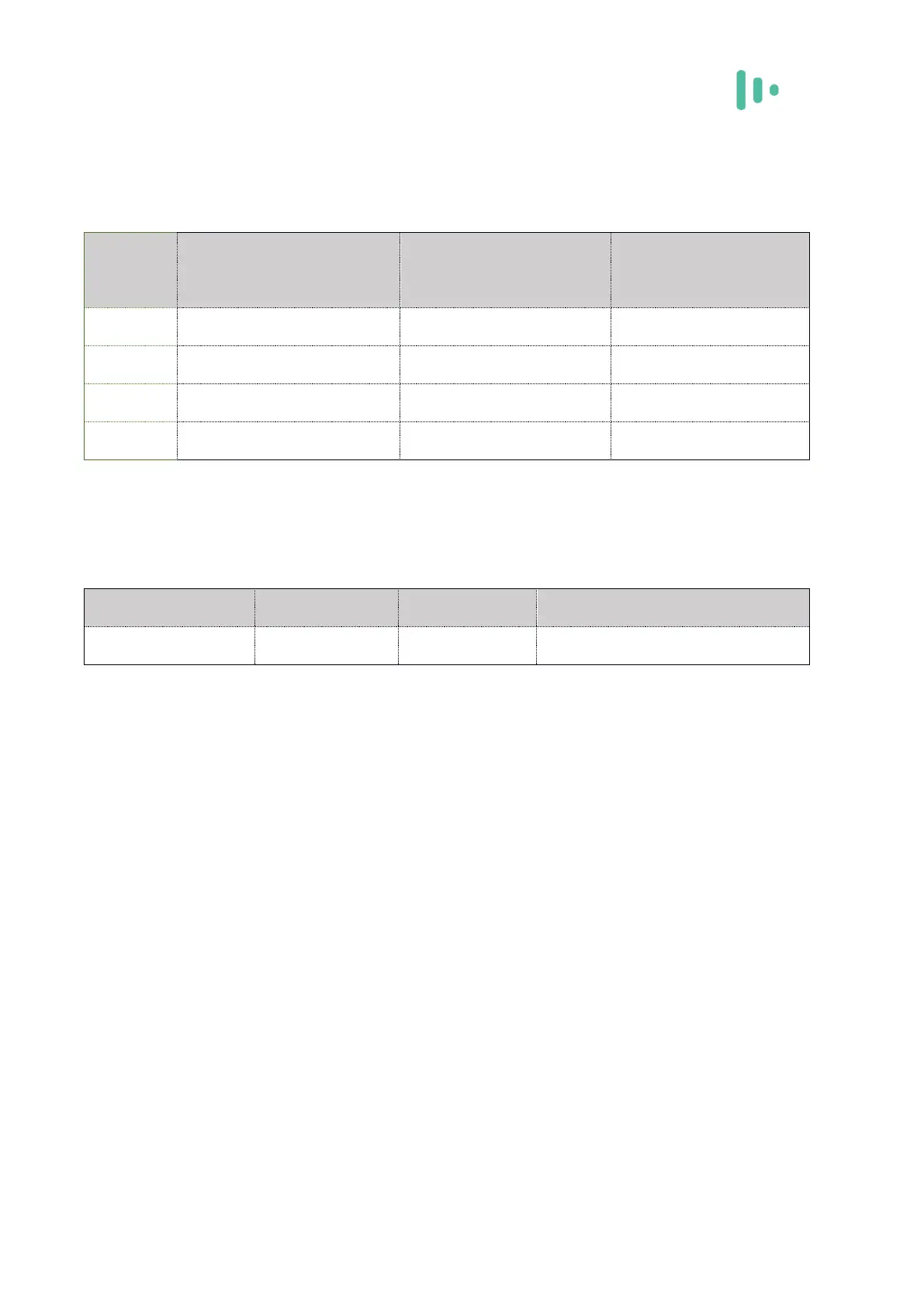
5.3 Module IO level
The C100QM/C10QM module IO levels are as follows:
Table 5-2 Electrical Characteristics of C100QM/C10QM Module
5.4 power supply
The C100QM/C10QM module input power requirements are as follows:
Table 5-3 C100QM/C10QM Module Operating Voltage
The power-on time of any interface of the module must not be earlier than the boot time
of the module, otherwise the module may be abnormal or damaged.
5.5 Electrostatic property
There is no overvoltage protection inside the C100QM/C10QM module. When the
module is used, the ESD needs to be protected to ensure product quality.
✧ EMC design recommendations:
✧ The USB port needs to add TVS on VDD, D+, D- for protection, and the TVS parasitic
capacitance on D+/D- is < 2 pF;
✧ The module's USIM card external pin needs to be TVS protected for parasitic
capacitance requirements < 10 pF.
✧ At the module input power supply, increase the TVS. It is recommended that the clamp
voltage VCL (Clamping Voltage) is less than 12 V and the peak power PPP (Peak Pulse