8
ENGLISH
EN
Introduction 8
Description 8
Technical data 8
Usage limits (IEC 60974-1) 8
How to lift up the system 8
Assembling the welding machine 9
Installation 10
Connection to the electrical supply 10
Gas connection 10
Instructions for use 10
Connection of torch and ground wire 10
Loading wire 11
Assembly of drive rollers 11
Welding 11
Aluminium welding 12
Maintenance 12
Possible problems and remedies 13
Troubleshooting table 13
Welding defects 13
Wiring diagram 80
Key to the electrical diagram 81
Colour key 84
Adjustment of electronic PCB 85
Meaning of graphic symbols on machine 86
Spare parts list 88-91
Entrainment mechanism 92
Drive mechanism 93
Ordering spare parts 94
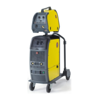
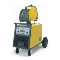
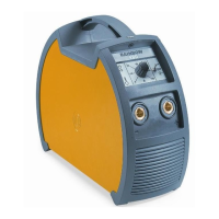
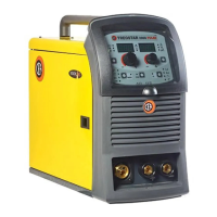
Description
Semiautomatic three-phase continuous wire welder with switch
adjustments and incorporated feeder, suitable for use with a
gas mixture or CO
2
and with cored wires with and without gas;
suitable for use in medium carpentry and body shops, in agri-
culture and for maintenance.
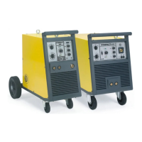
The main features of COMPACT welders are:
•
Exceptional welding characteristics with all materials as a re-
sult of inductance levelling.
• Excellent welding performance on thin metal sheets.
•
Provided with standard gas cylinder trolley with sturdy wheels
to facilitate movement.
•
Free-standing metal structure with front panel in special
shockproof fibre.
• Tough handle for ease of movement.
•
Adequate internal space for conveniently storing metal spools
(Max 300 mm - Max 20 kg).
• Euro torch connection.
•
42 V D.C. geared motor with electronic control of wire speed.
• 4 roll wire drawing unit.
• A gas solenoid valve.
• Switch for selecting 2-step and 4-step modes.
• Potentiometer for the wire speed adjustment.
• Potentiometer for “Burn back” with external adjustment.
• Potentiometer for motor start-up adjustment.
• Potentiometer with switch for adjusting spot-welding times.
Technical data
The technical data for this equipment is summarized in the ta-
ble 1.
Usage limits (IEC 60974-1)
The use of a welder is typically discontinuous, in that it is made
up of effective work periods (welding) and rest periods (for the
positioning of parts, the replacement of wire and underflushing
operations etc). This welding machine is dimensioned to supply
I
2
max nominal current (350 A), in complete safety, for a work
period amounting to (35%) of total usage time. The regulations
in force establish the total usage time to be 10 minutes. If the
permitted work cycle time is exceeded, an overheat cut-off oc-
curs to protect the components around the welder from dan-
gerous overheating. The yellow thermostat LED located on the
machine rack panel lights up when the overheating protection
trips. After several minutes the overheat cut-off rearms auto-
matically (yellow LED off) and the welder is ready for use again.
How to lift up the system
Before lifting the unit, open the bag containing the eyebolts (at-
tached to machine), remove the two eyebolts complete with fi-
bre washers and mount them on the upper part of the cover.
IMPORTANT: Only lift the unit using the two eyebolts.
The wire-feeder has a handle and a hook so that it can be
hung up.
NOTE: The lifting and transporting devices conform with Eu-
ropean regulations. Do not use other equipment to lift or trans-
port the feeder.
Introduction
Thank you for purchasing one of our products. Please read in-
structions on use in this manual as well as the safety rules
given in the attached booklet and follow them carefully to get
the best performance from the plant and be sure that the parts
have the longest service life possible. In the interest of custom-
ers, you are recommended to have maintenance and, where
necessary, repairs carried out by the workshops of our service
organisation, since they have suitable equipment and specially
trained personnel available. All our machinery and systems are
subject to continual development. We must therefore reserve
the right to modify their construction and properties.
 Loading...