8
ENGLISH
EN
Introduction 8
Description 8
Technical data 8
Usage limits (IEC 60974-1) 8
Assembling the welding machine 9
How to lift up the system 9
Installation 10
Connection to the electrical supply 10
Gas connection 10
Instructions for use 10
Connection for welding cables to welder 10
Connection of extension cable to wirefeeder 10
Welding 11
Aluminium welding 12
Maintenance 12
Possible problems and remedies 12
Troubleshooting table 13
Welding defects 13
Wiring diagram MAXI 405 80
Wiring diagram MAXI 505 81
Key to the electrical diagram 82
Colour key 83
Meaning of graphic symbols on machine 84
Meaning of graphic symbols on rating plate 85
Spare parts list 87-91
Ordering spare parts 92
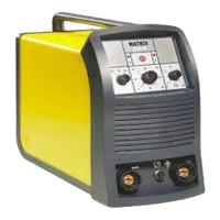
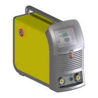
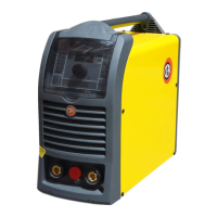
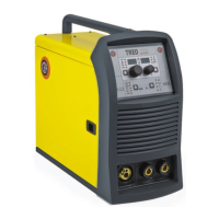
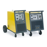
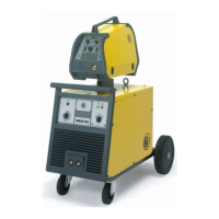
Description
SEAM WELD SYSTEM WITH SEPARATE WIRE FEEDER
REGULATED BY COMMUTATOR
Series of three-phase semi-automatic weld machines, with sep-
arate wire feeder, suited for industrial use for medium to large
scale steel structural works. The generators in the MAXI series,
which can be fitted with various kinds of wire feeders and var-
ious lengths of interconnecting generator-wire feeder cables,
are a complete answer to a whole range of usage, guarantee-
ing excellent welding performance for all materials with different
thickness, always with a steady arc in all positions. The main
features of the MAXI weld systems being:
• Strong and reliable.
• Excellent welding for all materials and various types of gas.
• Ideal for welding any metals used in industry.
• Innovative practical design.
•
Metallic supporting structure with front panel in anti-shock
fibre.
•
Slanting front panel with wide range of visibility from all an-
gles to facilitate reading and adjusting parameters.
• Controls protected against accidental blows.
• Strong ergonomic handle for moving about easily.
•
Provided with standard gas cylinder trolley with sturdy wheels
to facilitate movement.
The essential parts consist of:
• A direct voltage three-phase weld transformer.
• A weld current rectifier.
• A power contactor to insert transformer.
• Main switch (circuit breaker) and scaled change over switch
for weld voltage.
• Dual inductance setting for best weld bath in all positions.
•
A weld voltage fine regulation commutator (change-over-
switch).
• An inductor for improved weld pool in all positions.
• An ancillary safety voltage circuit (48Vac) to supply the wire
feeder.
•
Safety voltage ancillary system (48 Vac) to feed the pre-
heater outlet.
Technical data
The technical data for this equipment is summarized in the ta-
ble 1.
Usage limits (IEC 60974-1)
The use of a welder is typically discontinuous, in that it is made
up of effective work periods (welding) and rest periods (for the
positioning of parts, the replacement of wire and underflush-
ing operations etc). These welders are scaled to supply a com-
pletely safe rated maximum current (I2) of 400 A (MAXI 405)
- 500 A (MAXI 505) for a working period equalling 35% of total
time used. The regulations in force establish the total usage
time to be 10 minutes. If the permitted work cycle time is ex-
ceeded, an overheat cut-off occurs to protect the components
around the welder from dangerous overheating. The heat pro-
tection indicator light, located on the machine rack panel, lights
up when the heat protection device is working. After several
minutes the overheat cut-off rearms automatically and the weld-
er is ready for use again.
Introduction
Thank you for purchasing one of our products. Please read in-
structions on use in this manual as well as the safety rules
given in the attached booklet and follow them carefully to get
the best performance from the plant and be sure that the parts
have the longest service life possible. In the interest of custom-
ers, you are recommended to have maintenance and, where
necessary, repairs carried out by the workshops of our service
organisation, since they have suitable equipment and specially
trained personnel available. All our machinery and systems are
subject to continual development. We must therefore reserve
the right to modify their construction and properties.
 Loading...