9
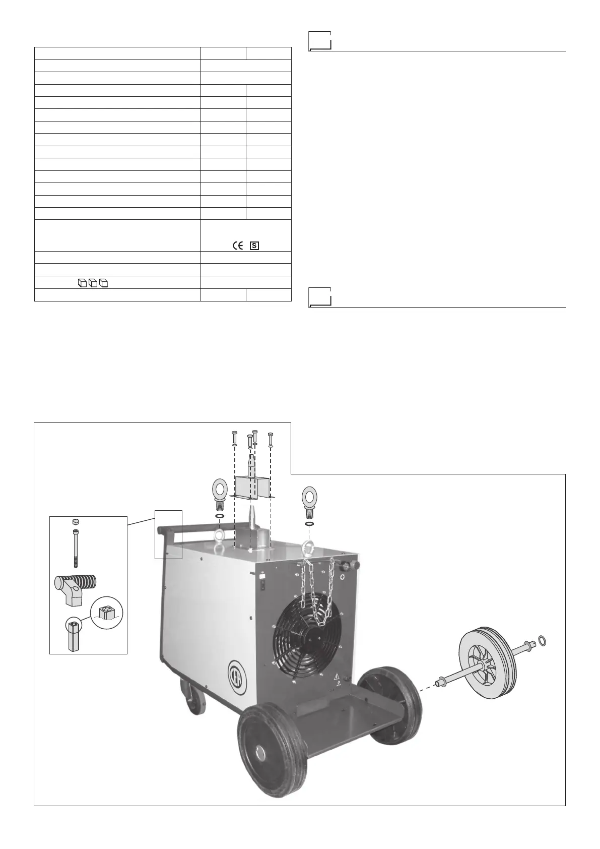
Assembling the welding machine
The standard composition of this welding installation consists
of:
• MAXI 405 or 505 generator.
• Earthing cable 4 m long (optional).
Accessories also include front and back wheels for moving
the welder, a chain for fastening the gas cylinder to the cylin-
der trolley easily, a handle especially for moving the machine
around manually, two eyebolts for lifting the machine off the
ground, a pivot to make sure the wire feeder is in the right po-
sition above the machine. Perform the following operations be-
fore using the machine:
• Open the case (box carton) and take out all the accessories
at the back of the welder.
•
Mount the back wheels following the description given in
Fig. A.
• Unpack the welder system.
•
Check that the welding apparatus is in good condition, other-
wise immediately inform the retailer or distributor.
•
Check that all ventilation grilles are open and that no objects
obstruct the free passage of air.
•
Lastly mount the handle, pivot and eyebolts following the de-
scription given in Fig. A.
How to lift up the system
Before lifting the unit, open the bag containing the eyebolts (at-
tached to machine), remove the two eyebolts complete with fi-
bre washers and mount them on the upper part of the cover.
IMPORTANT: Only lift the unit using the two eyebolts.
The wire-feeder has a handle and a hook so that it can be
hung up.
NOTE: The lifting and transporting devices conform with Eu-
ropean regulations. Do not use other equipment to lift or trans-
port the feeder.
Table 1
Model MAXI 405 MAXI 505
Three-phase power supply 50/60 Hz V 230/400
Mains supply: Z
max
Ω (*)
Power input @ I
2
Max kVA 19,0 24,2
Delayed fuse (I
2
@ 60%) A 35/20 40/25
Power factor / cosφ 0,96 0,97
Maximum efficiency degree η 0,75 0,71
Open circuit voltage V 20 ÷ 44 19 ÷ 51
№ of adjustments 20 30
Current range A 60 ÷ 400 60 ÷ 500
Duty cycle @ 100% (40°C) A 230 300
Duty cycle @ 60% (40°C) A 300 370
Duty cycle @ 35% (40°C) A 400 500
Wire diameter mm 0,6 ÷ 1,6 0,8 ÷ 2,0
Standards
IEC 60974-1
IEC 60974-10
Insulation class IP 23 S
Protection class H
Dimensions
mm 1060 - 780 - 600
Weight kg 99 113
(*) IMPORTANT:
•
This plant meets the requirements laid down in the EN/IEC 61000-
3-12 standard on harmonic currents.
•
This system, tested according to EN/IEC 61000-3-3, meets the re-
quirements of EN/IEC 61000-3-11.
FIG. A
2000H928
 Loading...