Ceiec Electric Technology
31
Control has the highest priority and can override any other applications. Next in the priority list
is Remote Control.
I residual Setpoints, Temperature Setpoint and Digital Input Setpoints share the same priority,
meaning that they can all be programmed to control the same Digital Output. This scheme is
equivalent to having an implicit Logical OR operation for the control of a Digital Output and may
be useful in providing a generic alarm output signal. However, the sharing of a Digital Output is
not recommended if the user intends to generate a control signal in response to a specific
setpoint condition.
Control Setpoints have the lowest priority. It should also be noted that if I residual and/or
Temperature inputs are equipped on the PMC-53, DO1 and DO2 will be reserved for the I residual
and Temperature Setpoints whether they are actually enabled or not. If a Control Setpoint is
programmed to trigger either DO1 or DO2 upon becoming active, the trigger action will not
succeed because Control Setpoints have the lowest priority and therefore will not be able to
control Digital Outputs when I residual and/or Temperature Inputs are present. However,
Control Setpoints can still be used for monitoring and alarming purpose via our PecStar®
Integrated Energy Management System.
4.1.3 Energy Pulse Outputs
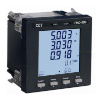
The PMC-53 comes standard with two front panel LED Pulse Outputs and can be equipped with two
additional Solid State Digital Outputs for kWh and kvarh pulsing. Energy pulsing can be enabled from
the front panel through the EN PULSE setup parameter. Energy Pulse Outputs are typically used for
accuracy testing. The pulse constant can be configured as 1000/3200/5000/6400/12800 imp/kxh, and
the pulse width is fixed at 80ms. If the PMC-53 is equipped with two Solid State Digital Outputs for
pulsing applications, Terminals DO1 and DO2 are reserved for kWh and kvarh Pulse Outputs,
respectively.
Note:
If the PMC-53M is equipped with the optional I residual and/or Temperature inputs and EN PULSE is
NOT ENABLED, these two front panel LEDs take on different meanings. The green kWh LED shows
the running state by blinking once per second, and the red kvarh LED is lit if there are any active I
residual or Temperature ALARM setpoints.
4.1.4 I residual Input
The PMC-53 optionally provides an I residual Input along with an external Residual Current Sensor
(see Appendix B) that has an input range of 20mA to 1200mA and an output range of 0 to 1.2V. The
outputs of the Residual Current Sensor are connected to the I residual input terminals of the PMC-53
if so equipped. This is illustrated in Figure 4-1 below.
The I residual input provides accurate ground fault monitoring and is mainly used for indirect
grounding protection to ensure personnel safety. Please refer to Section 4.3.3 for a complete
description of the I residual Setpoint operation.

 Loading...