Do you have a question about the CET PMC-53A and is the answer not in the manual?
Safety warning indicating severe injury or death risk if precautions are not followed.
Safety warning indicating potential personal injury or equipment damage if precautions are not followed.
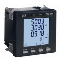
Provides an overview of the PMC-53A Intelligent Multifunction Meter, its features, and applications.
Details the key features of the PMC-53A, including ease of use, basic measurements, and advanced measurements.
Explains how the PMC-53A is used in Power and Energy Management Systems and its connectivity.
Provides contact details and website for obtaining additional product information and support.
Illustrates the physical components and connections of the PMC-53A meter with diagrams.
Provides the physical dimensions of the PMC-53A meter in front and side views.
Details the terminal dimensions, wire size, and maximum torque specifications for connections.
Explains the installation procedure and environmental requirements for mounting the PMC-53A meter.
Lists supported wiring modes for connecting the PMC-53A to various power systems.
Explains how to operate the PMC-53A using its front panel buttons and menu interface.
Describes the available data display options and measurements shown on the PMC-53A’s screen.
Details the U/I measurements and display screens available on the PMC-53A.
Lists the available Power measurements and their display options on the PMC-53A.
Outlines the Energy measurements (kWh, kvarh, kVAh) and their display formats on the PMC-53A.
Explains the Demand measurements (Present, Predicted, Peak) and their display on the PMC-53A.
Describes the Harmonics measurements (THD, TDD, K-Factor) and their display on the PMC-53A.
Details the Max./Min. Log measurements and display options on the PMC-53A.
Explains the Time of Use (TOU) measurements and display screens on the PMC-53A.
Describes the Input/Output (I/O) status and display options on the PMC-53A.
Explains the Sequence of Events (SOE) Log display and reset functionality on the PMC-53A.
Guides users on how to configure settings using the front panel, including password entry and parameter changes.
Details the process of making setup changes, including password entry and parameter modification.
Provides a visual representation of the meter's setup menu structure and available configuration options.
Lists and describes the various setup parameters for the PMC-53A, categorized by Basic, Comm., and Setpoint.
Describes the optional digital, pulse, analog, and RTD inputs and outputs available on the PMC-53A.
Details the functions and setup parameters for the PMC-53A's digital inputs.
Explains the applications and usage of the PMC-53A's digital outputs for alarming and control.
Describes the energy pulse outputs for kWh and kvarh pulsing, including setup parameters.
Explains the setup parameters and usage of the PMC-53A's optional analog input for measurements.
Details the setup parameters and functionality of the PMC-53A's optional analog output.
Describes the optional RTD inputs for temperature measurements and their compensation settings.
Covers the basic measurements related to power and energy provided by the PMC-53A.
Lists and describes the basic electrical measurements (U, I, kW, etc.) provided by the PMC-53A.
Details the energy measurements (kWh, kvarh, kVAh) for 3-phase and per-phase, including TOU.
Explains the interval energy measurements and their setup for real-time accumulation.
Describes the demand measurement setup parameters, including period and sliding windows.
Covers various power quality parameters like phase angles, harmonics, and unbalance.
Explains phase angle analysis for identifying relationships between voltage and current angles.
Details power quality parameters including harmonics (THD, TDD, K-Factor, Crest Factor).
Describes voltage and current unbalance measurements and calculation methods.
Explains user-programmable setpoints for control, alarming, and monitoring applications.
Covers logging functionalities like Max/Min Log, Peak Demand Log, and Monthly Energy Log.
Details the Max./Min. Log feature for recording parameter values with timestamps.
Explains the Peak Demand Log feature for recording peak demand values with timestamps.
Describes the monthly energy logging feature for storing energy data over 12 months.
Explains the optional daily and monthly freeze logs for energy and demand parameters.
Details the Sequence of Events (SOE) Log for storing events with timestamps.
Explains the optional data recorder log for capturing multiple parameters with configurable settings.
Describes the Time of Use (TOU) functionality for electricity pricing and energy accumulation.
Covers wiring error detection and diagnostic registers for checking possible problems.
Provides a detailed Modbus register map for basic measurements like U, I, kW, kvar, kVA, etc.
Details the Modbus registers for energy measurements (kWh, kvarh, kVAh) for 3-phase and per-phase.
Lists Modbus registers for total 3-phase energy measurements (Import, Export, Net, Total).
Lists Modbus registers for Phase A energy measurements, including TOU tariffs.
Lists Modbus registers for Phase B energy measurements, including TOU tariffs.
Lists Modbus registers for Phase C energy measurements, including TOU tariffs.
Details Modbus registers for interval energy measurements added in later firmware.
Lists Modbus registers for Digital Input pulse counters.
Provides Modbus registers for harmonic measurements, including power quality parameters.
Lists Modbus registers for power quality measurements like TDD, K-Factor, Crest-Factor.
Details Modbus registers for current harmonic measurements (THD, TOHD, TEHD, HDxx).
Details Modbus registers for voltage harmonic measurements (THD, TOHD, TEHD, HDxx).
Covers Modbus registers for Present Demands, Predicted Demands, and Peak Demand logs.
Lists Modbus registers for current demand values (Ia, Ib, Ic, kW, kvar, kVA).
Lists Modbus registers for predicted demand values (Ia, Ib, Ic, kW, kvar, kVA).
Details Modbus registers for peak demand logs for the current month.
Details Modbus registers for peak demand logs for the previous month.
Covers Modbus registers for Max./Min. logs of current and previous months.
Lists Modbus registers for the maximum log values of the current month.
Lists Modbus registers for the minimum log values of the current month.
Lists Modbus registers for the maximum log values of the previous month.
Lists Modbus registers for the minimum log values of the previous month.
Details Modbus registers for monthly energy logs, including import, export, net, and total values.
Explains the optional daily and monthly freeze logs for energy and demand parameters.
Details the Modbus registers for the daily freeze log, including index and data structure.
Details the Modbus registers for the monthly freeze log, including index and data structure.
Describes the SOE Log Pointer and data structure for recording events with timestamps.
Covers device setup parameters for communication, I/O, setpoints, and data recorders.
Details basic setup parameters like PT/CT ratios, wiring mode, THD calculation, and language.
Explains I/O setup parameters for digital inputs, outputs, pulse width, and analog configurations.
Details communication setup parameters for protocols, unit ID, baud rate, and configuration.
Covers setup parameters for setpoints, including type, parameters, limits, delays, and triggers.
Describes TOU setup parameters including tariff, season, daily profile, and alternate days.
Details basic TOU setup parameters like current tariff, season, daily profile, and day type.
Explains the setup parameters for seasons, including start dates and daily profiles.
Details the setup parameters for daily profiles, including period start times and tariffs.
Explains the setup parameters for alternate days, assigning daily profiles to specific dates.
Describes the registers for setting the meter's time and date using various formats.
Explains how to control digital outputs remotely using Modbus commands.
Details the registers and commands for clearing various logs and resetting meter data.
Provides information about the meter model, firmware version, protocol, and serial number.
Lists parameters available for data recording, categorized by real-time measurements.
Lists parameters available for data recording, categorized by power quality measurements.
Lists parameters available for data recording, categorized by energy measurements.
Lists parameters available for data recording, categorized by demand measurements.
Provides basic information about the PMC-53A's BACnet MS/TP protocol support and conformance.
Details the BACnet device objects supported by the PMC-53A, including properties and ranges.
Lists the N2 commands supported by the PMC-53A, including identification and override functions.
Provides a mapping table of PMC-53A AI points to N2 protocol parameters for analog input.
Details the DNP V3.0 profile, including supported levels, objects, and functions.
Describes the Level 1 implementation details for DNP-L1, including object requests and responses.
Explains the Control Relay Output objects and their response to function codes.
Details the 32-bit binary counters for primary readings and their format.
Describes the analog input primary readings and their corresponding points and units.
Lists technical specifications for voltage inputs, including range, overload, and burden.
Details technical specifications for current inputs, including range, overload, and burden.
Lists technical specifications for the optional I4 input, including range and starting current.
Provides technical specifications for the power supply, including standard and optional ranges.
Details technical specifications for digital inputs, including type, sampling, and hysteresis.
Provides technical specifications for digital outputs, including type and loading.
Lists technical specifications for pulse outputs, including type, isolation, and load limits.
Specifies installation torque values for current inputs and power supply connections.
Lists environmental conditions for operating and storing the meter, including temperature and humidity.
Provides mechanical characteristics like panel cutout, unit dimensions, and IP rating.
Specifies the accuracy and resolution for voltage measurements.
Specifies the accuracy and resolution for current measurements.
Specifies the accuracy for the I4 measurement.
Specifies the accuracy for kW, kvar, and kVA measurements.
Specifies the accuracy for kWh and kVAh measurements according to standards.
Specifies the accuracy for kvarh measurements according to standards.
Specifies the accuracy for Power Factor measurements.
Specifies the accuracy for frequency measurements.
Specifies the accuracy for THD measurements according to standards.
Specifies the accuracy for K-Factor measurements according to standards.
Specifies the accuracy for phase angle measurements.
Lists safety requirements and certifications for the PMC-53A according to various standards.
Details electromagnetic compatibility requirements and immunity tests based on CE EMC Directive.
Covers limits and methods for measuring radio disturbance characteristics and emission standards.
Lists mechanical tests performed on the PMC-53A, such as spring hammer and shock tests.
Explains the product code structure for the PMC-53A Intelligent Multifunction Meter and its options.
Provides contact information for CET Inc., including address, tel, fax, email, and website.
| Frequency | 50/60 Hz |
|---|---|
| AC Current Input | 5A |
| Communication | RS-485 |
| Measurement Range | 0-5A AC |
| Connector Type | Screw terminal |
| Operating Temperature | -10°C ~ +55°C |
| Storage Temperature | -20°C ~ +70°C |