CET Electric Technology
24
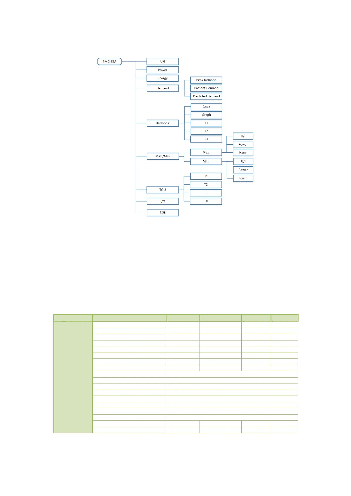
3.2 Data Display
Figure 3-2 Data Display Menu
Throughout this document, the phase-to-neutral notations of A/B/C and L1/L2/L3 as well as the phase-
to-phase notations of AB/BC/CA and L12/L23/L31 may be used interchangeably for specifying a certain
parameter to be a phase-to-neutral or phase-to-phase value, respectively.
The following sections illustrate the available measurements for each display option. Depending on the
Wiring Mode selected, certain measurements may not be available. For example, the per-phase Uln,
Uln Average, I4, per-phase kW, kvar, kVA and PF measurements are not available when the Wiring Mode
is set to 3P3W or 1P2W L-L.
3.2.1 U/I
Display 7 (Currents Angle)
Display 8 (Phasor Diagram)
U1 Real-time 1-cycle Waveform
U2 Real-time 1-cycle Waveform
U3 Real-time 1-cycle Waveform
I1 Real-time 1-cycle Waveform
I2 Real-time 1-cycle Waveform
I3 Real-time 1-cycle Waveform
Display 15 (Operating Time)
Operating Time (Running Hours)
* Available in Firmware V1.00.03 or later
#
Available in Firmware V1.00.06 or later
Table 3-2 U/I Display