CET Electric Technology
21
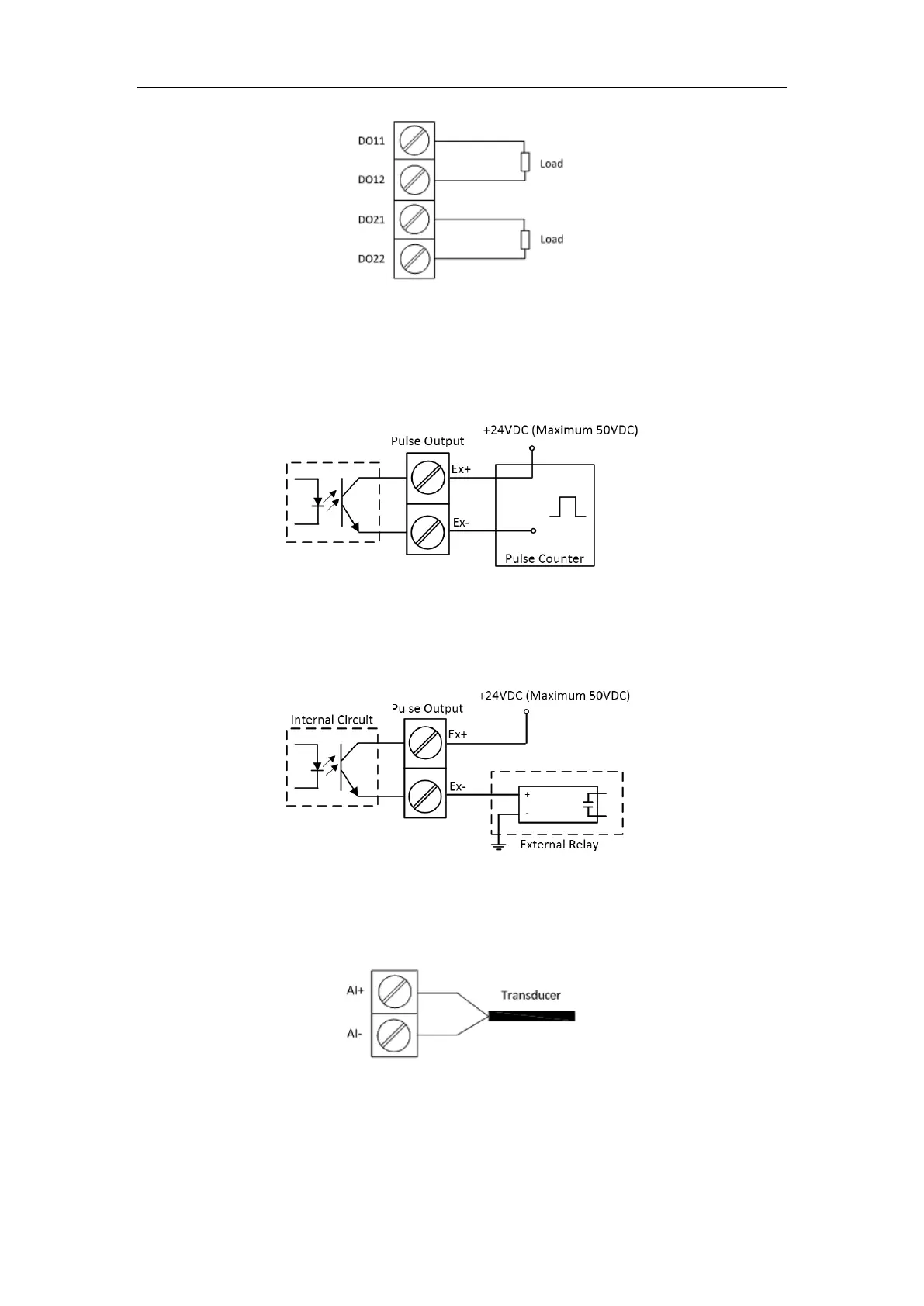
Figure 2-17 DO Connections
2.9 Pulse Output Wiring
The following figure illustrates the Pulse Output connections on the PMC-53A when the DO Control
Mode setup register is programmed for Energy Pulsing:
Figure 2-18 Pulse Output (Solid State Relay) Connections for Energy Pulsing
The following figure illustrates the Pulse Output (Solid State Relay) connections on the PMC-53A when
the DO Control Mode setup register is programmed for Remote Control/Alarm:
Figure 2-19 Pulse Output (Solid State Relay) Connections for Remote Control/Alarm
2.10 Analog Input Wiring
The following figure illustrates the Analog Input connections on the PMC-53A:
Figure 2-20 AI Connections
2.11 Analog Output Wiring
The following figure illustrates the Analog Output connections on the PMC-53A: