CET Electric Technology
38
There are 4 setup parameters:
Type: Select between 0-20mA or 4-20mA output.
AO Zero: Defines the zero scale value of the parameter when the Analog Output is 0 or 4 mA
according to the AO Type. The value ranges between -999,999 to +999,999.
AO Full: Defines the full scale value of the parameter when the Analog Output is 20 mA. The
value ranges between -999,999 and +999,999.
Key: Defines the parameter to which the Analog Output is proportional. The Analog Output
Parameters are listed in Table 3-13.
For example, an AO of 4-20mA is required to be proportional to Phase A current. The maximum value
of phase A current is 2000A, and the minimum value is 500A. As such, the Type parameter should be
programmed as 4-20mA. The Key parameter should be programmed with Ia (Phase A Current). The AO
FULL parameter should be programmed with the value 2000. The AO ZERO parameter should be
programmed with the value 500. Therefore, when Phase A Current is 500A or below, The AO output is
4mA. When Phase A Current is 2000A, the AO output is 20mA. When Phase A Current is 1250A, the AO
is (1250A-500A) x (20mA-4mA) / (2000A-500A) + 4mA = 12.00 (mA).
4.1.6 RTD Input
The PMC-53A optionally provides two RTD Inputs for temperature measurements. The PT100 sensors
are optional and not included. The 2-wire outputs of the PT100 sensor are connected to the RTD Input
of the PMC-53A if so equipped. The PMC-53A can provide accurate temperature monitoring with the
optional RTD inputs for measuring the temperature of the Neutral Conductor, Transformer or other
equipment. There is a RTD Compensation register for each channel which can be used to compensate
the measurement accuracy, and the compensation can be set according to formula:
RTD Compensation = 0.29xL where L ≤ 8 is the PT100 sensor’s cable length in m
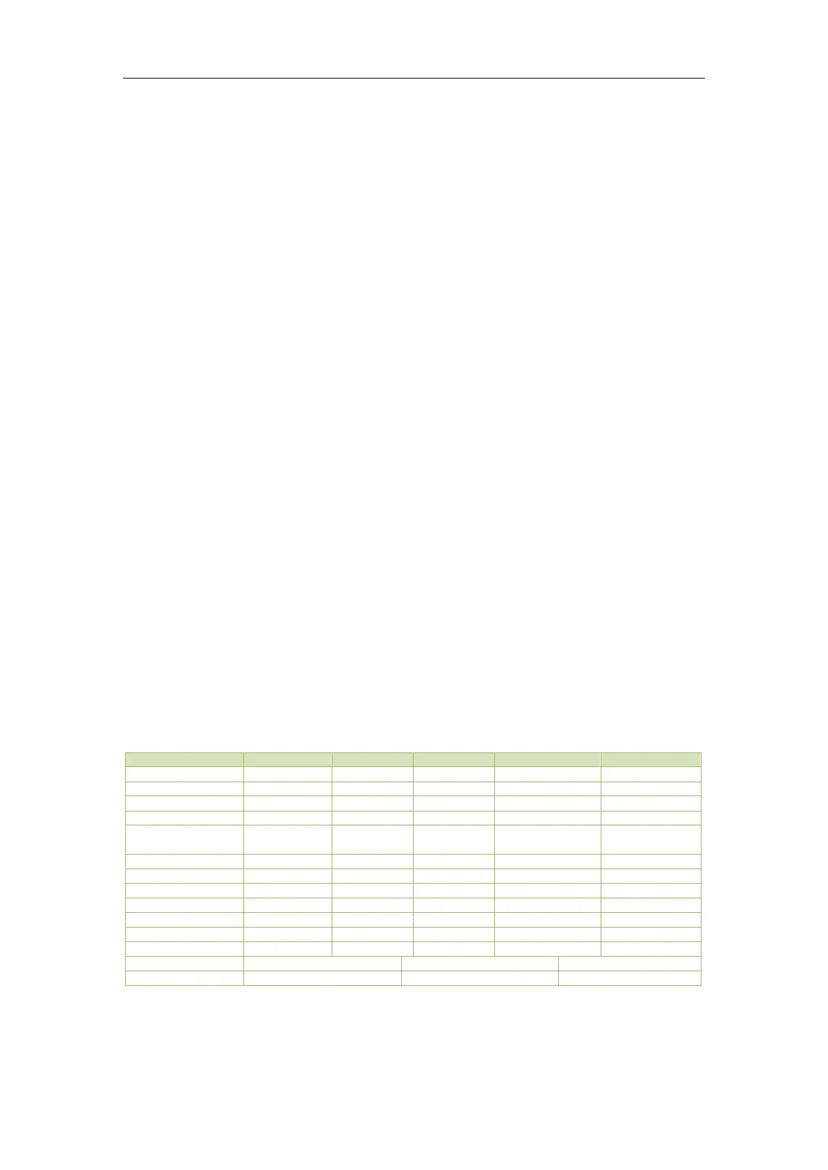
4.2 Power and Energy
4.2.1 Basic Measurements
The PMC-53A provides the following basic measurements which are available through the Front Panel
or communications.
* Available in Firmware V1.00.03 or later.
~ Available in Firmware V1.00.06 or later.
Table 4-2 Basic Measurements