CET Electric Technology
70
3) The Self-Read Time applies to both the Peak Demand Log as well as the Max./Min. Log and
supports the following three options:
A zero value means that the Self-Read will take place at 00:00 of the first day of each month.
A non-zero value means that the Self-Read will take place at a specific time and day based on
the formula: Self-Read Time = (Day x 100 + Hour) where 0 ≤ Hour ≤ 23 and 1 ≤ Day ≤ 28. For
example, the value 1512 means that the Self-Read will take place at 12:00pm on the 15th day
of each month.
A 0xFFFF value means the automatic self-read operation is disabled and the log will be
transferred manually.
4) The Delimiter setup register supports two options, 1 and 2:
Option 1: “,” is used as the x1000 delimiter and “.” as the decimal point (e.g. 123,456,789.0).
Option 2: “ ” is used as the x1000 delimiter and “,” as the decimal point (e.g. 123 456 789,0).
5) The Monthly Energy Log Self-Read Time and Monthly Freeze Self-Read Time support only two
options:
A zero value means that the Self-Read will take place at 00:00 of the first day of each month.
A non-zero value means that the Self-Read will take place at a specific time and day based on
the formula: Self-Read Time = Day * 100 + Hour where 0 ≤ Hour ≤ 23 and 1 ≤ Day ≤ 28. For
example, the value 1512 means that the Self-Read will take place at 12:00pm on the 15th day
of each month.
6) The Daily Freeze Self-Read Time can be set to a zero value or a non-zero value:
A zero value means that the Self-Read will take place at 00:00 everyday.
A non-zero value means that the Self-Read will take place at a specific time of the day based
on the formula: Self-Read time = (Hour x 100 + Min) where 0 ≤ Hour ≤ 23 and 0 ≤ Min ≤ 59. For
example, the value 1512 means that the Self-Read will take place at 15:12 of each day.
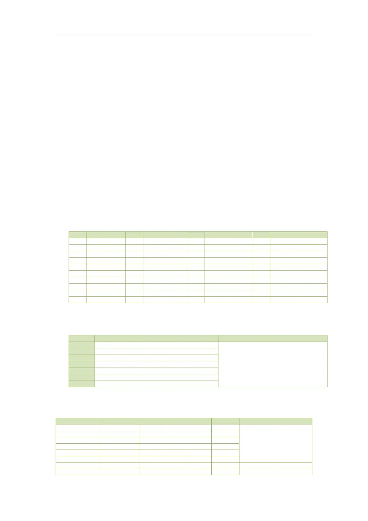
7) The following table illustrates the parameters that can be selected for display in the Default Display
screen.
*Available in Firmware V1.00.06 or later
Table 5-34 Default Display Parameters
8) The Interval Energy registers will be reset once the EN Period is changed.
9) The DNP Polling Objects are listed in table below:
Object 20: 32-Bit Binary Counters
Object 20: 16-Bit Binary Counters
Object 30: Analog Inputs Primary Readings
Object 40: Analog Output Status
Table 5-35 DNP Polling Objects
5.11.2 I/O Setup
0 = Digital Input*
1=Pulse Counting
2 =Tariff Switch
1