CET Electric Technology
41
harmonics). The higher the K-Factor, the greater the harmonic heating effect.
)(
)(
K
2
hh
1h
2
hh
1h
max
max
h
h
I
hI
Factor
where
I
h
= h
th
Harmonic Current in RMS
h
max
= Highest harmonic order
4.3.2.4 Crest Factor
Crest Factor is defined as the Peak to Average Ratio (PAR), and its calculation is illustrated below:
where
|X|
peak
= Peak amplitude of the waveform
X
rms
= RMS value
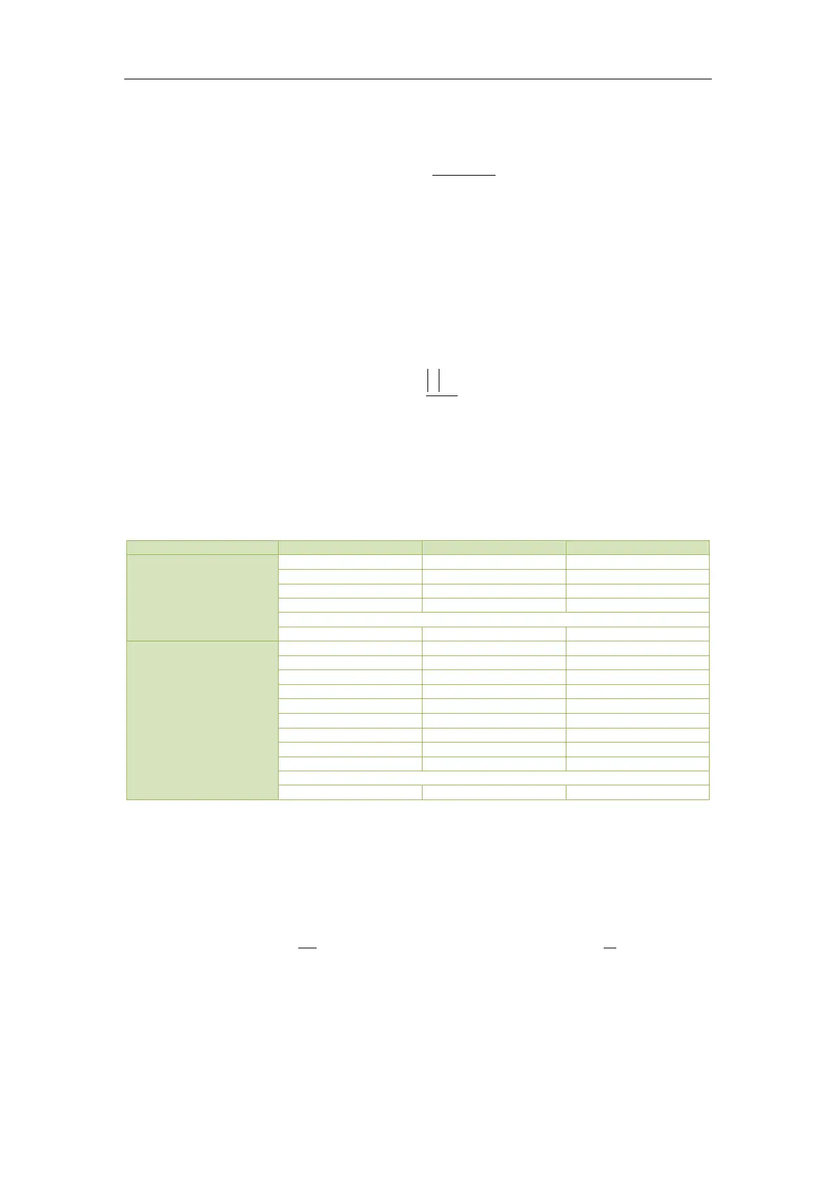
The following table illustrates the available Voltage and Current Harmonics measurements on the PMC-
53A.
Table 4-5 Harmonic Measurements
4.3.3 Unbalance
The PMC-53A provides Voltage and Current Unbalance measurements. The calculation method of
Voltage and Current Unbalances are listed below:
Voltage Unbalance =
Current Unbalance =
where
V1, V2 are the Positive and Negative Sequence Components for Voltage, respectively.
and
I1, I2 are the Positive and Negative Sequence Components for Current, respectively.