CET Electric Technology
68
2) Clear Historical Monthly Energy Log means to clear the Monthly Energy Log of the last 1 to 12
months, excluding the Monthly Energy Log for the Present Month.
3) Clear All Data via Front Panel or Communication means to clear 3-Phase Total Energy registers,
Phase A/B/C Energy registers, Monthly Energy Log of the Present Month, All Peak Demands, All
Max./Min. Logs, Device Operating Time, All DI Pulse Counters, All DR Logs and All Freeze Logs.
4) Clear All Energy Registers means to clear the 3-Ø Total and Per-Phase energy registers.
5) Clear Present Monthly Energy Log means to clear the Monthly Energy Log of the Present Month.
6) Clear Historical Monthly Energy Log means to clear Monthly Energy Log of the last 1 to 12 months,
excluding the Monthly Energy Log for the Present Month.
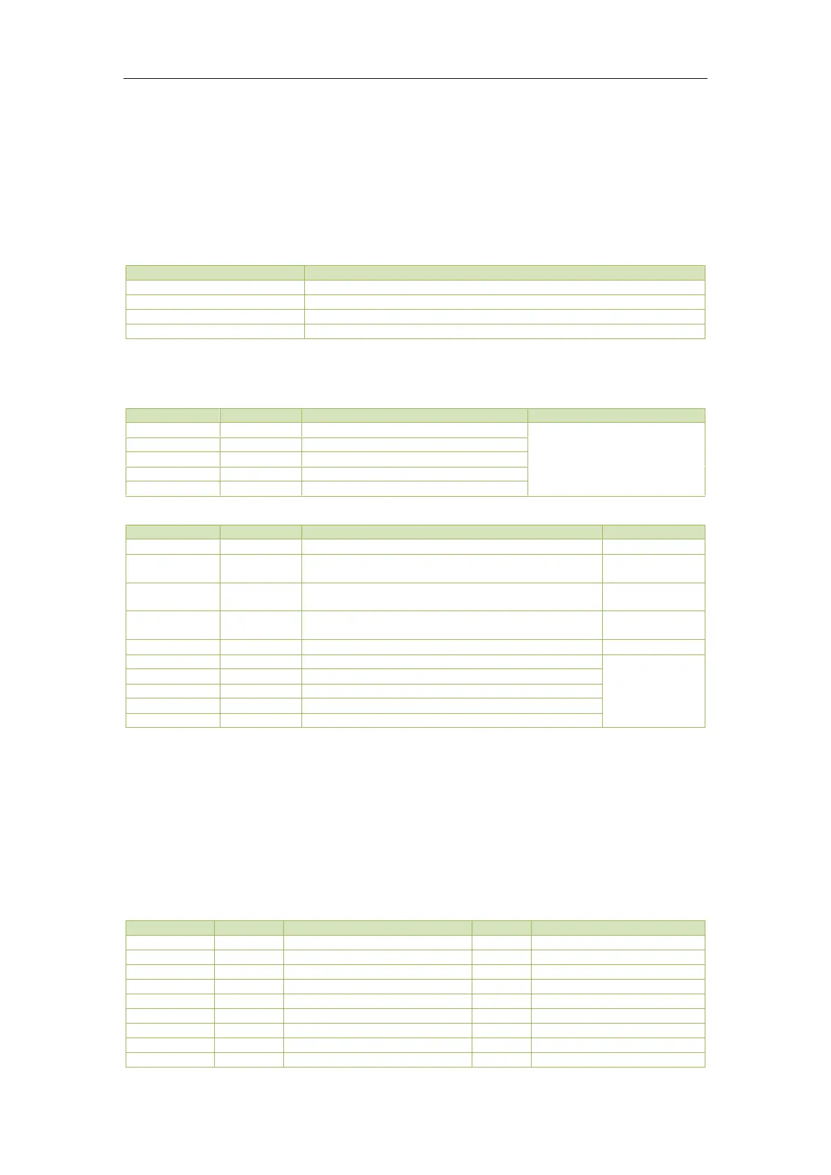
7) The event values of Switch TOU Schedule are illustrated in the table below:
Switch Schedule 1 to Schedule 2 manually
Switch Schedule 2 to Schedule 1 manually
Switch Schedule 1 to Schedule 2 automatically
Switch Schedule 2 to Schedule 1 automatically
Table 5-30 TOU Switch Records
5.10 Data Recorder Log (Optional)
See Table 5-32
Standard DR Log Structure
Table 5-31 DR Log
High-order Byte: Year (0-99)
Low-order Byte: Month (1-12)
High-order Byte: Day (1-31)
Low-order Byte: Hour (0-23)
High-order Byte: Minute (0-59)
Low-order Byte: Second (0-59)
Table 5-32 DR Data Buffer Structure
Notes:
1) Writing n to the DR Log X Pointer register will load the Log Record at pointer position n into the
DR Log X Buffer from the device’s memory.
2) Writing a pointer value that points to a Log Record that is either already expired or has not been
generated yet to the DR Log X Pointer register will generate an exception response with the Illegal
Data Value error code (0x03) as defined by the Modbus protocol.
5.11 Device Setup
5.11.1 Basic Setup Parameters