Ceiec Electric Technology
32
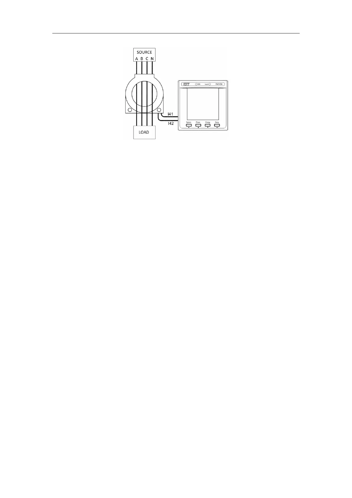
Figure 4-1 I Residual Connections
4.1.5 Temperature Input
The PMC-53 optionally provides a RTD Temperature Input along with an external RTD Temperature
Sensor (see Appendix C) to provide temperature measurement. The outputs of the Temperature
Sensor are connected to the Temperature Input of the PMC-53 if so equipped.
The Temperature Input provides accurate temperature monitoring and is mainly used for measuring
the temperature of the Neutral Conductor, Transformer or other equipment that requires temperature
monitoring. Please refer to Section 4.3.4 for a complete description of the Temperature Setpoint
operation.
4.2 Power and Energy
4.2.1 Voltage and Current Phase Angles
Phase analysis is used to identify the angle relationship between the three-phase voltages and
currents.
For Wye connected systems, the per phase difference of the current and voltage angles should
correspond to the per phase PF. For example, if the power factor is 0.5 Lag and the voltage phase
angles are 0.0°, 240.0° and 120.0°, the current phase angles should have the values of -60.0°, 180.0°
and 60.0°.
For Delta connected systems, the current phasors lag line-to-line voltage phasors by 30°. For
example, if the total power factor for a balanced 3-phase system is 0.5 Lag and the line-to-line voltage
phase angles are 0.0°, 240.0° and 120.0°, the current phase angles should have the values of -90.0°,
150.0° and 30.0°.
4.2.2 Energy
Basic energy parameters include active energy (kWh), reactive energy (kvarh) and apparent energy
(kVAh) with a resolution of 0.1k and a maximum value of ±99,999,999.9. When the maximum value
is reached, the energy registers will automatically roll over to zero.
The energy can be reset manually or preset to user-defined values through the front panel or via
communications.
The PMC-53 provides the following energy measurements:
 Loading...
